CMOY Power Supply Issues
Jun 4, 2007 at 3:32 AM Post #31 of 47
the reason I ask for a handdrawn schematic is when tracing the actual circuit you will find the problems in the process. When drawing using a computer you are putting down what you think it "should be", it is not the actual wiring any more.

about using resistors as rail spliters: 4.7K as spliters will only give you loose bass, nothing solid. If you can make sure both batteries are always the same %, center tap ground is always better. Because ALL of your headphone currents goes through the ground.

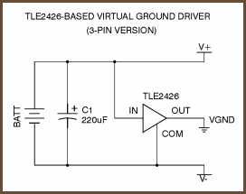
The problem might be the chip, per that schematic in the picture, if you use a BJT opamp you are guaranteed to have DC offsets which, when combined with the low ground current capability (due to using 4.7Ks as spliter), will give you off center voltage readings (one being higher than the other, instead of being the same). The 2132 being a FET input opamp should not do that, but if the opamp itself is damaged when handling-- the FET input is very sensitive to static discharges, that is why they are always shipped in a silver bag -- they can create DC offsets.

Try another chip and see if that solves the problem. IC's are pretty cheap.
very_evil_smiley.gif
 
Jun 4, 2007 at 9:33 AM Post #32 of 47
Well, One of the things I have on order is a TLE2426 Rail Splitter (I'm pulling that from memory) and I'll be swapping that for the resistors, and then moving to just one cap across the batteries like in this:

tle2426clp.png


That'll be only after replacing the chip and caps to see if those got fried.
 
Jun 4, 2007 at 12:51 PM Post #33 of 47
Stepping back from a project for a day or two can be very helpful.

Drawing your actual circuit will tell you what you actually have built.

Then if the circuit is OK go over the circuit with a magnifier-I like the over the head binocular style-and your DMM or VOM set to continuity to look for shorts and defective solder joints.

Be sure all your ground connections are intact.

Change out the op/amp as you already plan to.

I use the two resistor power supply arrangement and it has worked well so your problem is elsewhere.

Cleaning off the flux may help too. There are instructions in many posts.

Sometimes I will set up a circuit on "plugboard" to see if I like it and substitute parts--this might be fun in the future for you.

Don't give up. So often the problem for me has been shockingly simple, but overlooked. It is good practice.

F
 
Jun 4, 2007 at 4:07 PM Post #34 of 47
See attached. The rows in the red rectangles should be connected together, and to the + or - cap lead (but not connected between rectangles). The green rectangle rows are your virtual ground, and should also be connected together, as well as to the other cap lead on each side. I know you redid the jumpers from Tangent's plan, just make sure that things are really connected together. The orange rectangles are Tangent's "M" jumpers which tie the feedback loop together and provide a pad for the output connections. Make sure these are connected together also.

Radioshack sells a TL082 opamp which will work, if you don't have another good opamp on hand. It won't sound very good, but you could at least verify the chip that way:

http://www.radioshack.com/product/in...tId=2062594&cp
 
Jun 4, 2007 at 10:12 PM Post #35 of 47
I took a magnifying glass and dental pick to the bottom of the board and cleaned all the areas between pads - scraping until I had removed all the flux from between the pads. I don't have any alcohol pure enough to wash the board with, I'll grab some tomorrow.

Pars, I checked each pad in the nodes you drew - they are all connected properly. All my custom jumpers show less than half an ohm of resistance also, so they work as well.

My Digi-Key order just shipped, so near the end of the week I'll be able to swap amps around.

+14.8, -2.4 are my readings with out headphones plugged in.
 
Jun 5, 2007 at 1:25 AM Post #36 of 47
the TLE is not gonna solve your problem. with that kind of reading even without the headphone plugged in, the TLE can get fryed easily......Trace and hand draw the acatual circuit and see if there is any thing wrong.

It is probably the chip itself.
 
Jun 5, 2007 at 2:13 AM Post #37 of 47
my 2 cents, its the chip. your PSU circuit is fine, you're getting +8.62 & -8.6 volts.
 
Jun 7, 2007 at 10:31 PM Post #38 of 47
'Twas indeed the Amp chip. I popped a new one in last night and got +8.62 and -8.60. Set up works beautifully. I took it to my soccer game later that night and succeeded in blowing up a set of ear buds!

100_1466.jpg

100_1467.jpg

100_1468.jpg


I had fun making this and I've got a few friends that want one... A bit of side income??

Thanks again to everyone that offered advice and help!

-Plarzy
 
Jun 8, 2007 at 7:08 AM Post #40 of 47
Quote:

Originally Posted by Plarzy /img/forum/go_quote.gif
'Twas indeed the Amp chip. I popped a new one in last night and got +8.62 and -8.60. Set up works beautifully. I took it to my soccer game later that night and succeeded in blowing up a set of ear buds!

~snip~

I had fun making this and I've got a few friends that want one... A bit of side income??

Thanks again to everyone that offered advice and help!

-Plarzy


HAHA! I hope they were free or cheepies you blewup, time to Upgrade! Same thing with me and my friends, I have atleast 3 who want one of my CMoy amps when I order the boards.
 
Jun 9, 2007 at 9:32 PM Post #43 of 47
Quote:

Originally Posted by Plarzy /img/forum/go_quote.gif
Yeah, I had stopped at Best Buy on the way home and grabbed a few of their $0.96 earbuds to blow up - I didn't want to ruin my decent sony cans.

Are you going to be using the Radio Shack protoboard, or are you getting PCB boards from somewhere??


I am getting my boards made by Olimex
 
Jun 10, 2007 at 3:34 AM Post #44 of 47
Joshadot:

Cool site. Are you going to be selling some of the boards? Dost thou havest pics of the design?

--------------------------------------------------------

Now that I've finally gotten it working, I've been testing to see how much it amplifies the sound, and in all honesty, I can't tell any kind of difference between the sound volumes of the mp3 player, and the amp on full. Am I mis-understanding the purpose of the amp, or do I have another problem?
 
Jun 10, 2007 at 9:33 AM Post #45 of 47
I should be ordering the boards this coming Monday. I'll make a new post when I order them, or maybe when they arrive. Board is 1.55" tall by 1.30" wide.

Eagle3D view:
cmoypd2.jpg


Board Layout
layoutig1.png


Printed Board:
layout2xx8.png


Board Traces:
tracesgu1.png
 

Users who are viewing this thread

Back
Top