Here are two relatively simple fixes:
First:
Alessandro MS1 transducer magnet dislodgement fix
Grado, which also makes Alessandro, is known to have shoddy workmanship in their headphone construction and often being seen as part of its 'old school charm'. So it is not that surprising when someone on a local headphone forum reached out to me last year asking for help to fix his MS-1 that has suddenly lost its right channel. I took the headphone in and immediately saw two common Grado issues - (1) the magnet on the right driver has dislodged from the driver itself, and (2) the right driver housing was broken from the headband at the pivot. It was like the two issues were related as the driver housing must had dropped on the ground causing the dislodgement of the magnet when the housing was broken from the headband. Of course, Grado known to use weak glue to secure the magnet isn't helping either.
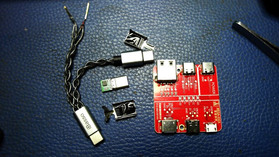
Tools and parts needed:
1) Hot air gun, or hair dryer as alternative
2) Headphone glue (i.e. B7000), super glue and hot glue.

You can tell from the grill that the magnet has dislodged as the copper coil is clearly visible,

The driver housing is glued together by Grado using hot glue, which means a hot air gun can easily soften the old glue enough to take them apart. Carefu not to overheat the plastic housing and cause it to deform. You can see on the picture below, the magnet is still holding on to the backside by just a thread.. To do this properly, I actually remove the magnet from the back completely to remove all the old glue residue from not just the magnet but also the hot glue on the housing itself.

With all the cleaning up done and making sure no debris/dust in-between the diaphragm and copper coil, the magnet is glued back using B7000 glue around the edge of the magnet. Do make sure the coil is properly aligned into the magnet. Once the B7000 glue is sufficiently dried, I place a few tiny drop of super glue on the seam to make sure the magnet will be extra secured.

Once I tested to be sure the right driver has came back to life, I hot glued the housing back. Hot glue is not really the best method to put headphone together, but at least it will make taking them aprt fairly easy in the future as well. After the housing is glued together, I super glued the headband back to the pivot. It is important that you use really good quality super glue as the pivot area is a very common failure point on most Grado. My preferred choice of super glue is from ERGO Switzerland.
 Afterthought:
 The fix is itself a completely success with the MS-1 going back to fully functional. However, given the chance I would have also preferred to (1) rebuild / reinforce the left driver's magnet with a tiny bit of super glue, consider that its glue is probably degraded as well, and (2) change the whole headband + pivot altogether. However, given it is not my headphone and the owner decided a working headphone is more than enough, I ended up sending the MS-1 back to him as it is.
------------------------------------------------------------------------
Second:
Sony WF-1000XM4 battery replacement
I got my WF-1000XM4 as soon as it was launched back in mid 2021, and as many early XM4 owner (*and perhaps also applied to most TWS owner) would know that the batteries, especially the one inside the earpiece, does degrade quite noticeably after a year or two. For me, it becomes a big issues about a month ago when I noticed both my XM4 earpiece have degraded to such a point that they can only last for 10~15 minutes before completely drained (*and ironically, just before Sony released a new firmware that should help to prolong / preserve the battery life). The good news is that replacing battery on XM4 is far easier than than of Airpod, requiring no soldering or any sophisticated technique / skill. I also opt to install a new battery for the charging case though the original battery seems to still function normally. Note that XM4 battery replacement guide / video can be found all over the place, so I am not going to write a detailed guide but just focus on what I think is important point
Tools and parts needed:
1) Replacement batteries (*for the earpiece, ZeniPower Z55H is stock replacement, VARTA CP1254 could also work in theory. For case battery, I opt for Cameron Sino)
2) A small vise and padding materials.
3) Glue, and recommending G-S Hypo Cement
4) Smartphone repair tool kit, naming a plastics guitar pick, small screw driver, and an insulated tweezer.
First, this is a technique I learned from a Japanese youtuber video on how to literally pop open the earpiece. Most other seems to advise using hot air to lightly heat up the earpieces then prying it open on the seam. But I find the Japanese technique is even better by using a small vise, but besure to use some padding material in order not to scratch the housing. Place the earpiece in the vise and VERY slowly clamp it together till you hear a faint popping sound, then immediately loose the vise. You should notice the seam has opened up slightly and you can use the guitar pick to pry them open.

Note in the picture below that there is a flex wire connecting the two half so you will need to disconnect it before pulling the two apart. BTW, the replacement ZeniPower Z55H battery I got from Aliexpress don't quite look 100% identical (especially on the marking) to the stock batteries I pulled from XM4, which bakes the question on whether these replacements are genuine ZeniPower or not. They do however function normally regardless. Please refer to youtube video on how to pull the battery out, just note take you should do it slowly as to not damage the double sided tape since you need to reuse them to hold the new battery back into the original position.

Once the new battery are installed on both earpieces, put them back into the charging case to see if them will charge and function normally before you seal the earpiece's two half back together. To seal the earpiece off and get back some water resistance, glue mush be used. While any headphone glue can be used, I find G-S Hypo Cement to be excellent in this area as it allows for very precise application with just a tiny amount to get the job done. You don't want to put too much glue in as there is a possibility that we might need to replace the battery again in a year or two. With G-S, just applies a tiny amount all around the edge, then clamping the earpieces down in the vise for a solid 30 minutes or so should be enough. I do recommend you leave them in the vise longer if you can.

Below is the battery for the changing case,

The charging cradle is held insides the case with just 4 internal clips as indicated with the arrows. Push the guitar pick from seam in the front (as shown in picture) to pop the clip, then slowly work you way around the edge / body to the back to pop the clip on the opposite side. Then repeat the process on the other side.

Here is another way to see those 4 clips once the cradle is removed.

Now you can remove the 2 screw that hold the top cover. Technically you don't need to remove it if you don't want to, but I find it easier to replace the battery when the top cover is not in the way,.

Next, disconnect the battery first (*the white connector in picture below). The battery itself is sandwiched between the bottom plastic frame and a grayish cover, where they are hold to the top plastic frame with just 4 clips (two are indicated by arrows below). Pop those clip and the bottom frame along with battery section will fall down. ,
 DO NOTE
 that the wireless charging coil underneath the bottom frame is still attached to the top as it is soldered to the PCB on the top frame. With careful handling, you shouldn't need to remove the coil to access the battery.

Battery cover can be popped out easily, but the battery itself is double taped to the bottom frame. The bottom frame is super soft so you can't put too much force on it. My suggestion is to use the guitar pick to slowly pry the battery up from the double sided tape.

Once the old battery is out, I will suggest you plug the new battery into the connector temporarily to test if charging (including charging the case as well as charging the earpieces) is working or not before attempting on putting everything back together. Once testing is done, disconnect the battery again and start to putting the whole thing back in reverse.

Connect the battery last and do a final testing before pushing the charging cradle back into the case. Then you are all done.
 Afterthought:
 As sophisticated as it looks, WF-1000XM4's batteries are surprisingly easy to replace. I charged the reborn XM4 overnight and used it for a few days, and it would seems it works almost as good as when it was new. Hopefully I'll get a few more years out of it before another battery replacement is required.


") Maybe make a 2-3 hole via drill
Maybe make a 2-3 hole via drill


