Chameleon DAC listening and modifications
Jul 14, 2010 at 7:34 AM Post #1,066 of 1,158
BTW, i have to mention that the support i got direct from Michael is excellent. I've been emailing him back and forth and he's going to send me a new power supply board for $30, which is only the postage.
 
Great services and support.
 
 
Jul 14, 2010 at 7:53 AM Post #1,067 of 1,158


Quote:
HI rhodes54,
 
It's the voltage coming out of the power supply into the dac board. 24V is when i wired the PSU up with the yellow wires and 13v is went i wired the PSU up with the blue wire (wires from the transformer).
 
so in short, when i measured the DC power output from the PSU into dac board (no connected) the voltage reading i got is as above, which is crazily high. I though my  meter was faulty but i measured other devices and my meter showed the correct reading so it wasn't my meter.
 
I've been having weird voltage reading ever since i got this dac, so i guess the PSU finally had enough.

 
If these high voltages are coming from your PSU output you might have some damage on your DAC. Luckily most parts of the digital boards are safe because of their 3.3V regulators. You might have ruined your DAC Chips (but you ordered new ones anyway, right?) and the XO's are directly connected to the +5V, that's it.
 
Great to hear that Michael will send you a new PSU board but can you please check the things I pointed out before (measuring the 10R resistor, the AC voltages directly on the transformer, etc?) and let me know to see if we can trace the problem?
 
 
Jul 14, 2010 at 12:03 PM Post #1,068 of 1,158
I get it. Which means if I put my last 110ohm resistor inline, meaning using 110 instead of 47 in the places you indicate, I will have both iput working and isolated but at 110R.
 
Did you ever try 100R before settling on 47R?

 
Quote:
 
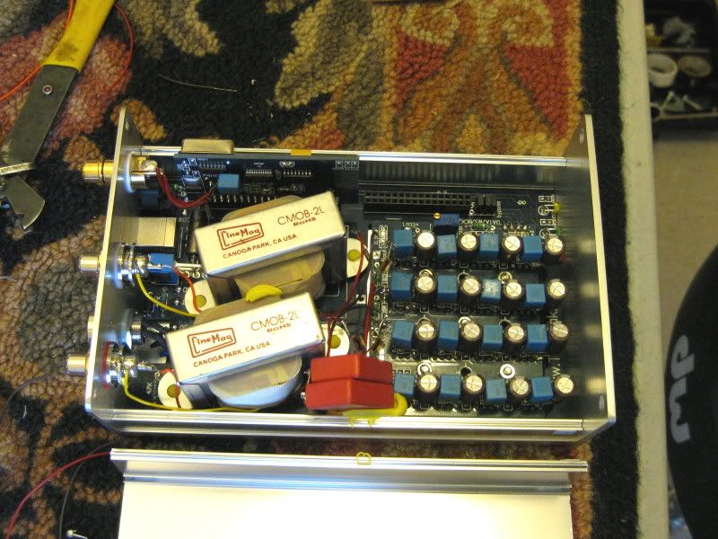
Hi Pat, No they aren't in series. Check this picture to get the idea:


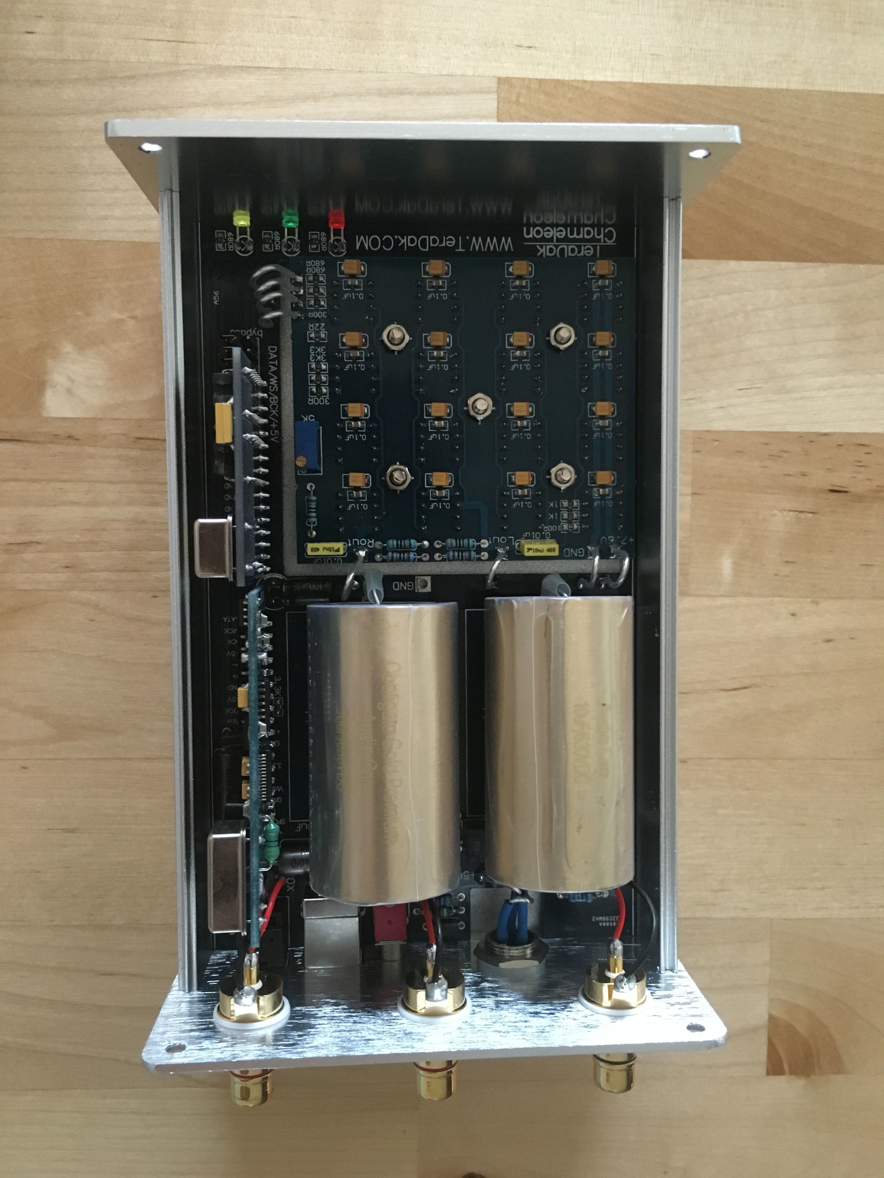
This means both the wm8805 and the USB receiver get a 47R resistor each. For the timebeing you have two options:
1. Leave the 110R resistor in place and solder two pieces of solid wire instead of the 47R resistors (see pic below). Now your Chameleon is still fully functioning (both USB and S/PDIF) though you will have reflections between the receiverchips.


2. Remove your 110R resistor and put a peace of solid wire instead and place the 110R resistor on the spots of one of the 47R resistors. The top resistor (leg 3&4) is leading to the SP/DIF receiver, the bottem resistor (leg 10&11) is leading to the USB receiver. Now you won't have reflections but either one of the two inputs will work.


Jul 15, 2010 at 5:00 AM Post #1,069 of 1,158


Quote:
I get it. Which means if I put my last 110ohm resistor inline, meaning using 110 instead of 47 in the places you indicate, I will have both iput working and isolated but at 110R.
 
Did you ever try 100R before settling on 47R?


That will work fine I think. The new digital boards of the Chameleon also work with 2 x 100R. They probably used 100R because they had them on hand which makes it cheaper for them to produce. I played a while without resistors at all. That worked too :)
 
Jul 15, 2010 at 8:24 AM Post #1,070 of 1,158

 
Quote:
 
If these high voltages are coming from your PSU output you might have some damage on your DAC. Luckily most parts of the digital boards are safe because of their 3.3V regulators. You might have ruined your DAC Chips (but you ordered new ones anyway, right?) and the XO's are directly connected to the +5V, that's it.
 
Great to hear that Michael will send you a new PSU board but can you please check the things I pointed out before (measuring the 10R resistor, the AC voltages directly on the transformer, etc?) and let me know to see if we can trace the problem?


yeah i order 16 new chips, chances are i fried my current ones anyway.
 
the 10r resister is not burnt and measured 10r
AC voltage from the transfer is 11-12vac blue wires, 14-15 vc yellow wires..
 
once i received the new supply board from michael, i am thinking of using a toroidal transformer, do you recommended that?
 
what do you think of this PSU, http://www.audio-gd.com/Pro/diy/PSU09/PSU09EN.htm
 
for $47 delivered may be worth trying..
 
Jul 16, 2010 at 5:04 AM Post #1,071 of 1,158
Quote:
yeah i order 16 new chips, chances are i fried my current ones anyway.
 
the 10r resister is not burnt and measured 10r
AC voltage from the transfer is 11-12vac blue wires, 14-15 vc yellow wires..
 
once i received the new supply board from michael, i am thinking of using a toroidal transformer, do you recommended that?
 
what do you think of this PSU, http://www.audio-gd.com/Pro/diy/PSU09/PSU09EN.htm
 
for $47 delivered may be worth trying..

 
At least your transformer is still ok. I would not change it to a toroidal transformer because the transformer they use now is good. The only reason I changed it to toroidials is because they are RFI/EMI shielded.
 
I personally think that the audio-gd PSU won't be much better than the DC-30W. If I look at the schematics they could be family. :)
 
 
Jul 17, 2010 at 4:46 PM Post #1,072 of 1,158


Quote:
That will work fine I think. The new digital boards of the Chameleon also work with 2 x 100R. They probably used 100R because they had them on hand which makes it cheaper for them to produce. I played a while without resistors at all. That worked too :)

I replaced my "commercial grade" (Radio Shack) 67 ohm resistors with a Vishay Metal Film 47 ohm units (CMF5547). Very noticeable improvement. I chose the Vishay's because they are precision and they are rated for high frequency use. Without any absolute proof I would give the majority of credit for the better sound to the quality of the resistors rather than the change in resistance. The change in resistance does not change the clock output voltage going to the chipsets by that much. They are mostly there as "decoupling" resistors if I am not mistaken. Without an oscilloscope I cannot see the difference between the output from one type of resistor from the other. I have to just listen. Granted, I may be overstating the case but that is why I will leave it up to others to try it and either confirm or deny my findings. The resistors are pretty cheap anyway.
 
 
Aug 21, 2010 at 6:30 PM Post #1,073 of 1,158
Battery Power Results
I was going to try using LiFePo batteries on my DAC so I tried my Optima Red Top battery beforehand. After more research I realized that they both had about the same internal resistance (about 3mOhms). Of course, the use of the RedTop is discussed all over the web so one can easily reach a different conclusion than I have just by reading. (snark) 
In any event I first hooked up my DAC chips to the battery and left the 5 volt rail alone. I set the voltage to the chips (7.8 volts) by using resistors (10 watt). A very easy comparison to make as the batteries were simply  more "quiet". By that I mean a blacker background. I believe that this is due to the lower noise floor of the DAC chips. Very nice improvement along the lines of replacing the 12 MHz clock. Another step in the direction of a more relaxed sound but with higher resolution. It was easy to hear deeper into the mix than ever before with disc after disc.
After that I put the rest of the DAC on the battery I got a little more of the same effect just not as much as the DAC chips alone. Still, if someone is going to battery, might as well. I did not put my 24 MHz clock on the battery as I had the Tentlabs power supply for that module and it requires 12 volts so isolating if from the 12 volts coming in is a little tougher.
Speaking of isolation, I used 27 ohm dropping resistors for the other two regulators that I use (see my other posts) for the digital boards. The 27 ohms units dropped the voltage to about 9 volts to feed the regulators. I also used de-coupling caps after the resistors to bleed any potential noise to ground and not back into the 12 volt rail. I mistakenly used non-polar caps in these positions at first. Lame amateur mistake there. Just allowed noise to circulate freely.
Now admittedly this is not a cheap thing for most to try as the battery is pricey whether you use a Red Top or a LiFePo due to the fact that our DAC's draw so much current compared to a normal one chip DAC. Count on a total of about 1.2 amps. I happen to have a Red Top in use for my 26 tube preamp heater circuit. I just tapped into that line. Any noise added would be easily heard as it was before I put in the proper polarized caps.
The sound is really a significant improvement over even my improved DC-30 setup. Of course, the cost is an issue for anyone not in possession of a non-SLA battery to play with.
Now, in relation to the snark I opened with. The Red Top has proponents and detractors (as anything on the forums do). I do not dismiss the findings of others in relation to the devices powered by the battery. I have heard for myself Lithium Ion batteries on the original Valab DAC and would concur that batteries do not always sound better. It may be the fact that I have the Film Reservoir Mod and the added DAC chip BlackGates and film caps installed but there is no loss of dynamics with my setup. The sense is of slightly more dynamics as the total noise floor has been reduced. Very relaxed and open sound.
Tony
 
Sep 5, 2010 at 3:23 PM Post #1,074 of 1,158
So I joined the transformer crowd. Well not a crowd actually, maybe just Pat and me.
smile.gif
  I went for the half nickel content. Just put them in and they are playing a break in disc as I write. Will let you know in a few days or maybe tomorrow what I think.
 
Chameleon2.jpg

 
Sep 5, 2010 at 7:57 PM Post #1,075 of 1,158
OK, I have a problem and I know there are a couple others with trannys...Newk Yuler, yes? Sound is so much more relaxed and detailed (in a good way) then the caps. But I have a ground 60hz hum/buzz with I turn up the volume and it wasn't there with the caps. I'm using two tx2575 175R on each primary leg as per Pat's diagram. As you can see from the pic in previous post, the trannys are inside the dac. Are they two close... to themselves, the input board, the DC on the board under them? They are attached with yellow artists putty/glue, like Blue Tac so they aren't directly on the board and not touching any other metal or trace.
 
Sep 6, 2010 at 3:57 AM Post #1,077 of 1,158
Hi guys, 
 
I was just wondering, for me to order this dac (I am this close)  I need to know that it implements a high frequency filter that cuts out the crap above 20khz.  I can't seem to find this information anywhere.  Also, I don't really plan to mod it, is it still a worthwhile dac unmodded?  Thanks.
 
Sep 6, 2010 at 5:20 PM Post #1,079 of 1,158
With Pat's help I managed to sort out the hum problems after installing the TXs. In post 1074 you can see I had them in the case side by side. Connected it to the system and had a ground hum that went up and down with the volume. Pulled 'em out and put them on top of the case at right angles to each other and reconnected. Same hum. When I got the dac originally and had not done any mods I had to remove the earth ground because it caused a severe ground loop with the amp. So I had been running transport, dac, pre without earth ground and amp with earth ground...dead silent. Pulled caps and installed TXs as per Pat's diagram...a separate 175r from each leg of primary + and - to ground. Big time hum that went up and down with the volume. I cured it by reconnecting the earth ground on the dac. Dead silent again. Love those little electrons. I may try moving them together again to see if they interact with each other. I'll post the outcome if I do this.
 
Sep 7, 2010 at 4:59 AM Post #1,080 of 1,158


Quote:
With Pat's help I managed to sort out the hum problems after installing the TXs. In post 1074 you can see I had them in the case side by side. Connected it to the system and had a ground hum that went up and down with the volume. Pulled 'em out and put them on top of the case at right angles to each other and reconnected. Same hum. When I got the dac originally and had not done any mods I had to remove the earth ground because it caused a severe ground loop with the amp. So I had been running transport, dac, pre without earth ground and amp with earth ground...dead silent. Pulled caps and installed TXs as per Pat's diagram...a separate 175r from each leg of primary + and - to ground. Big time hum that went up and down with the volume. I cured it by reconnecting the earth ground on the dac. Dead silent again. Love those little electrons. I may try moving them together again to see if they interact with each other. I'll post the outcome if I do this.


Hi Chris,  I ordered a pair of transformers over a month ago and I am still waiting....  Grr...  What output caps did you have before switching over to the cinemags?  I have a pair of Duelands & Texas Components in my VALAB.  Just curious on your setup before the cinemags and the SQ differences.
 

Users who are viewing this thread

Back
Top