Carrie USB-Powered Headphone Amplifier
Oct 22, 2010 at 2:22 PM Post #826 of 913
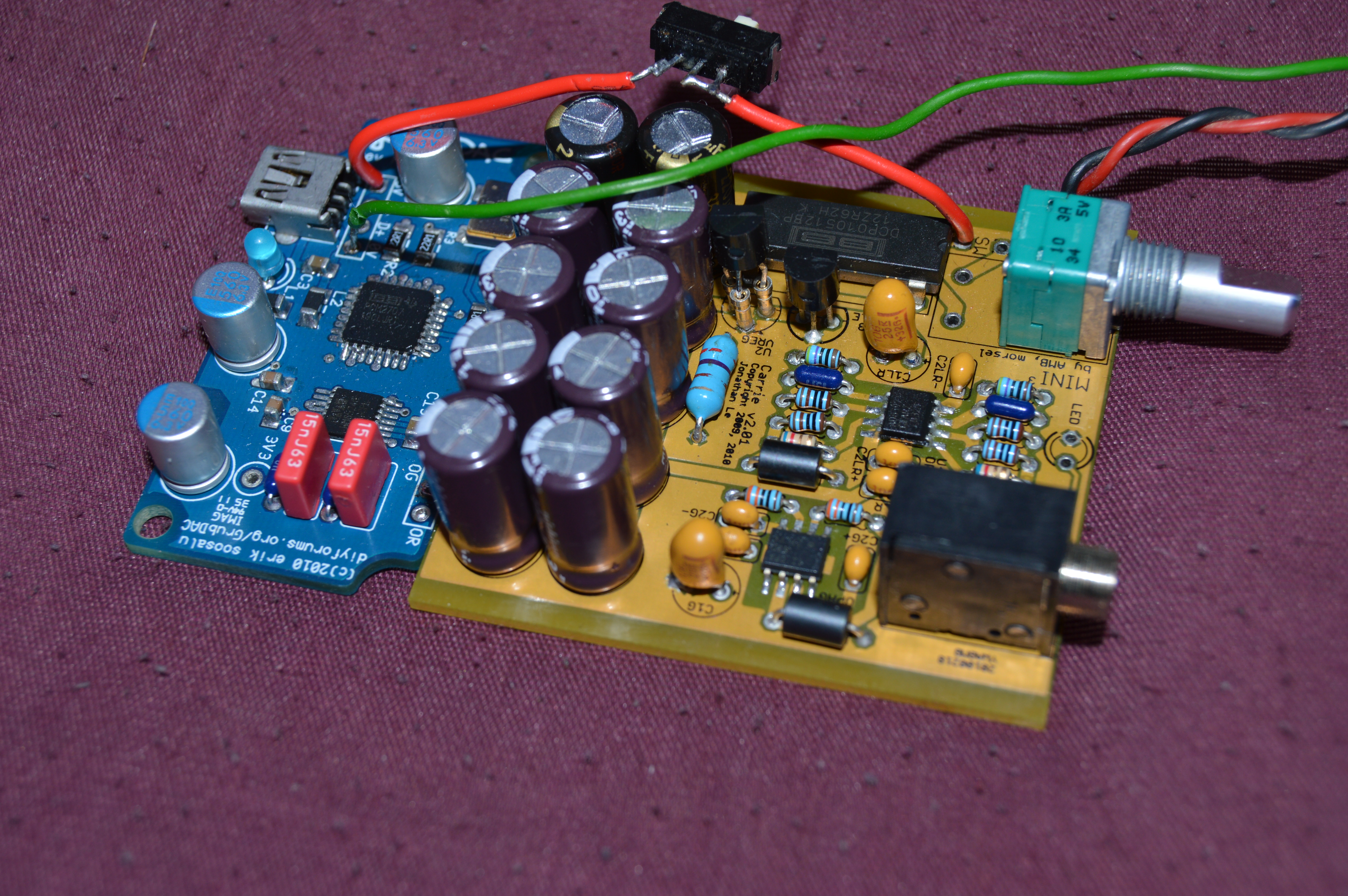
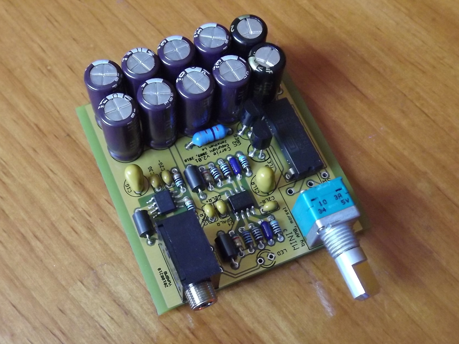
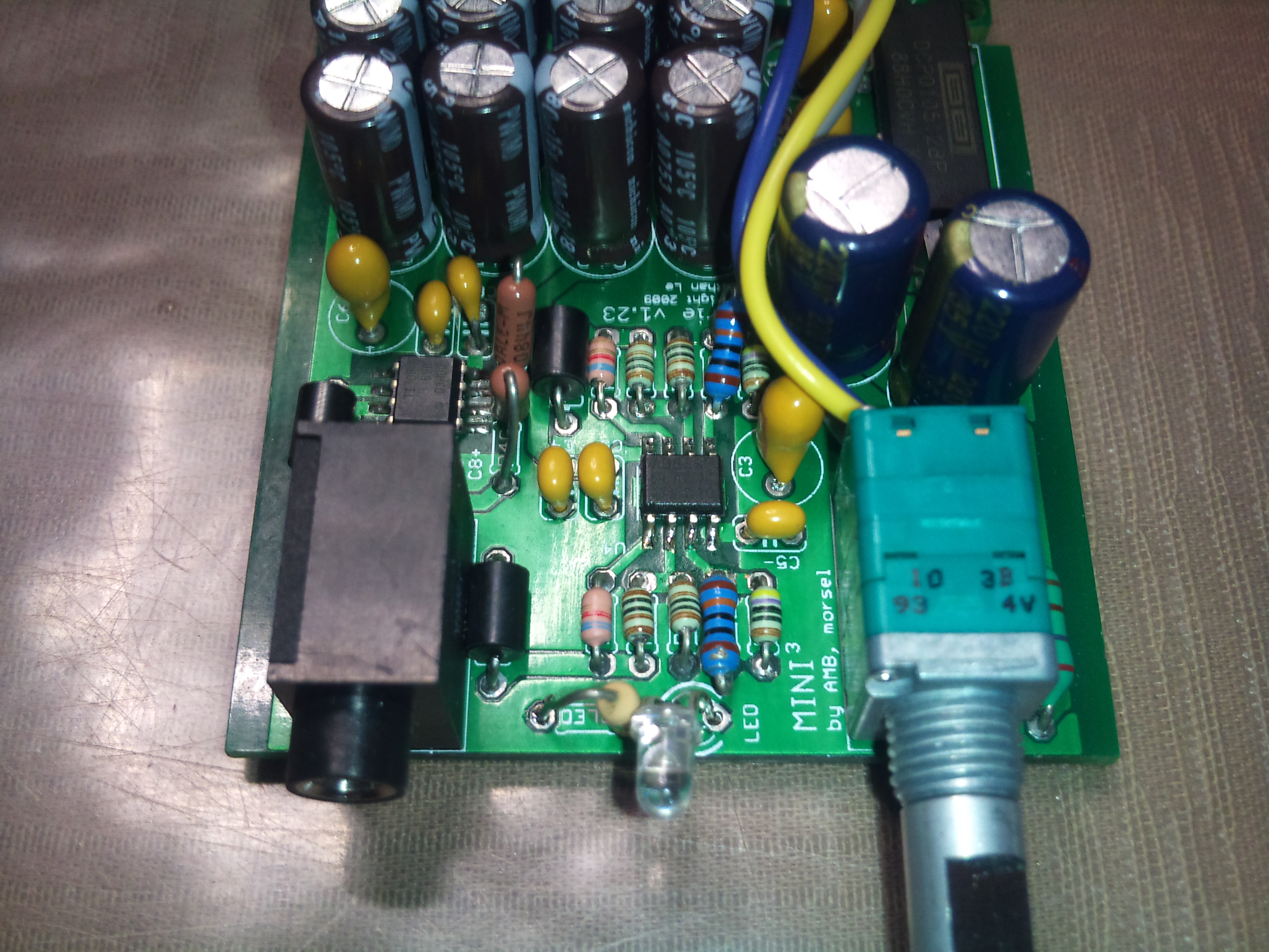
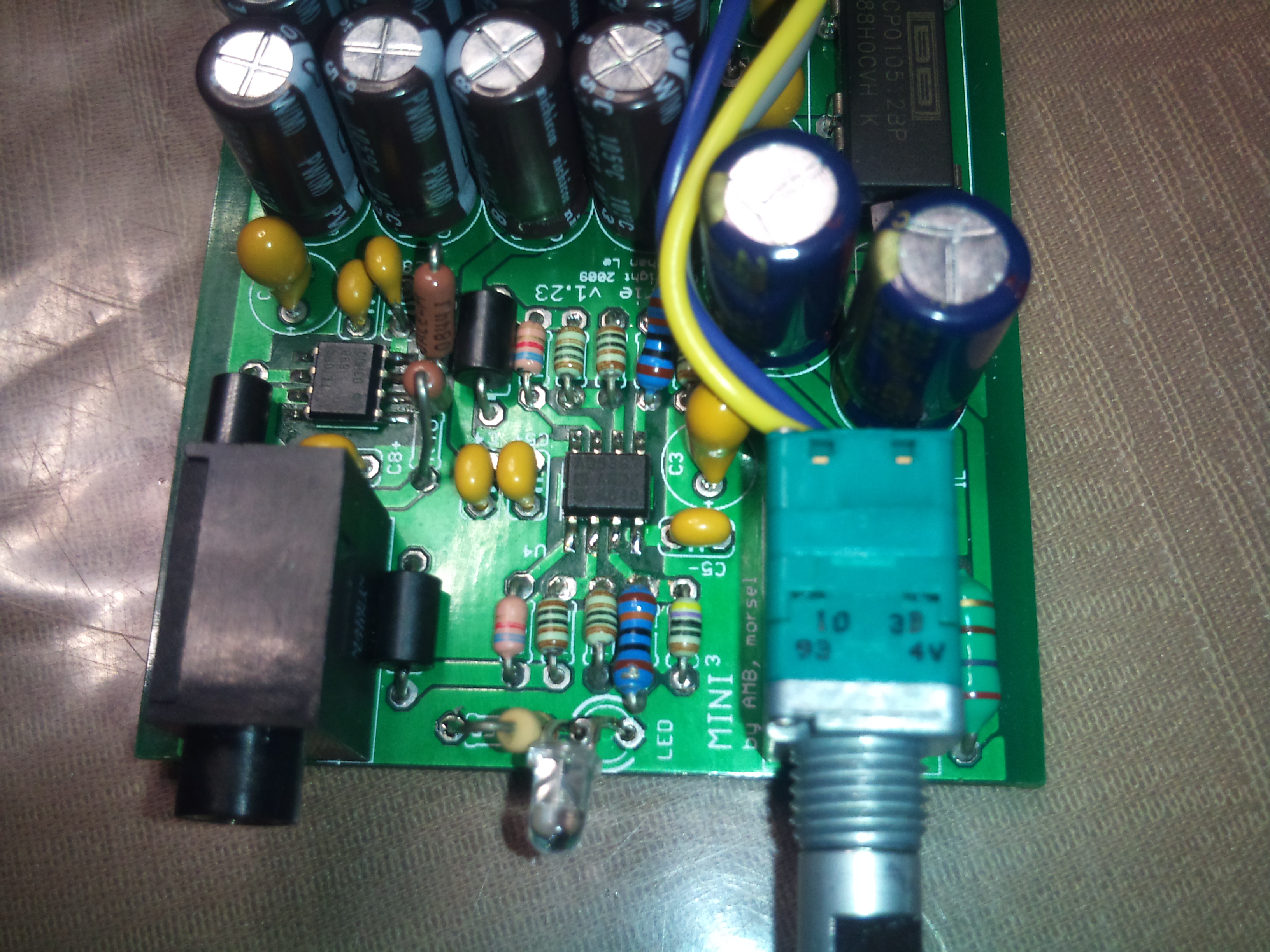
i can see that there are caps both rail to rail and rail to ground, i was wondering if the rail to ground ones were necessary / what they're for though, i thought you only needed caps from rail to rail when using a tle.
 
thanks for the link though, the bom will come in handy when i finally get around to starting my build
smily_headphones1.gif

 
Oct 22, 2010 at 3:20 PM Post #829 of 913
hmm so i saw a piece i'd overlooked before on tangent's page on virtual grounds that explains the caps are for sourcing/sinking current. for the purpose it's being used, it shouldn't be sourcing any current, only sinking right? and doesn't the active ground take care of that?
 
also, how can i calculate how much current is being sinked? it would change based on the impedance of the headphones being driven right? i built my brother a cmoy like a month ago and i didn't put any caps from rail to ground. he's only driving a hd555 so it's fine for now, but i want to figure out where he should start worrying if he was to upgrade.
 
Oct 30, 2010 at 7:20 PM Post #830 of 913
Amps like the MINT, Mini^3, M^3, PIMETA v1, META42, PPA v2 and v1 have large series capacitances on the output of the TLE2426; PIMETA v2 uses smaller values. From Tangent's article on virtual grounds,
 
Quote:
Output caps can be a good thing if the rail splitter has a fairly low output current limit. That’s the situation in the MINT amp, for example. The TLE2426 has an output current limit of between 20 to 40 mA, depending on operating conditions. When it goes into current limiting, its output goes to the negative rail, which would make for a massive shift in the virtual ground point, so we cannot allow this to happen. A heavy headphone load could indeed exceed 20 mA, so putting caps on the ouptut of the TLE2426 saves the design.

 
Checking the TLE2426 datasheet, Figure 17 on page 17 shows how the load capacitance affects the TLE2426's stability. Not much is needed, but the size of the caps is mostly due to balancing the rails as in Tangent's article.
 
Nov 21, 2010 at 3:04 PM Post #832 of 913
I've finished my grub and starting on the amp now. So I a not sure I understand your question, but my plan is to hook the 5V pad on the amp to the 5V pad, right next to J1, on the Grub.
You would use the SW pad for an off board power switch.
 
Nov 21, 2010 at 11:43 PM Post #834 of 913
I ran into this problem when mating my grubdac to the carrie board.  I had to grab the + leg from C5 and wire it up to the 5V pad on the carrie board.  Mine would not startup when I hooked the 5V pad from the grub to the 5V on the carrie.  
Just route a single wire from C5+ leg to your 5V pad on the carrie.  the C5 leg doesn't go anywhere just wire the C5+ pad to the 5V pad on the carrie board and it should be good...
 
Dec 20, 2010 at 4:21 PM Post #836 of 913
Well another one lives. Just completed the build from the recent group buy. Sounds swell, thanks to joneeboi for all the work.
Little story to go with this one.
I wired it up to a grub DAC prototype version and it did not fire up. I was getting just shy of 1volt at the output of the converter, ahh I thought need to try the C5 thing. Sure enough, that did it, sweet music came pouring out. I was very happy. I had to take it apart because now my power lead was short and would not reach the C5 position. I used solder braid and cleaned the holes on both the ground and power on the carrie and the ground on the grub, made the new connections... Nothing, the grub fired up but the carrie stayed dark. Drat, I started to take measurements, the grub had 5.25 at the USB V+ and Gnd, it had 5.25 at C5 and USB Gnd, and the same at the carrie V+ in and Gnd, Hmmm... turn on the carrie and the voltage everywhere but the USB V+ went to 2.75v. I was truly mystified and upset. To make a long story short I checked everything several times and then while checking continuity, I discovered that the ground pads on the grub were separate! I must have used a it too much heat cleaning the holes. The ground was contiguous everywhere but to the ground pad I used to connect the two boards. I soldered a bit of left over resistor lead between the two ground pads on the grub, and viola! It was working.
 
Jul 17, 2011 at 4:50 AM Post #838 of 913
Interesting project.  This is just what I and another member on the forum were looking for.
A couple questions (pardon if they have been asked):
1.  What purpose does the switch in the pot serve in this circuit?  In regular mini^3 it is obviously used to turn it off and conserve battery, however, as this amp is bus powered, there is really no point in turning it off as the DAC will still be on.
2.  Will there be another batch of boards soon?  If not, would you share the schematic&board files with us?
 
Nov 19, 2011 at 4:55 PM Post #839 of 913
Wow, it's been a while since I read this thread. Sorry to take so long to respond, FLACm0nkEy.
 
1) After all this time, I wonder myself why I used the switched pot. I was trying to limit inrush current, but I don't think I needed it after all. There's a better version of the pot with logarithmic tracking and no switch, which would have saved board space and better performance. It was mostly a convenient solution. I was wrong.
 
2) I won't give it all away, but someone else may be starting up a group buy. Would if I could. I plan to start another one in 2012, but I'm too busy lately.
 
Mar 3, 2012 at 10:01 PM Post #840 of 913
I just finished my Carrie (hooked up to a GrubDAC).  First listen was quite impressive.  I had to get the 5V from C5 on the GrubDAC.
 
Thanks to joneeboi and colbatmute for their efforts.


Users who are viewing this thread

Back
Top