Carrie USB-Powered Headphone Amplifier
Jul 25, 2013 at 10:52 PM Post #856 of 913
Quote:
Hi all.
Sorry fo my google translate.
 
I have grubDAC. It works perfectly. :)
 
I need Carry USB Hedamp. Where i can order kit ?
 
Thx.

I'm sorry, but Joneeboi was the designer and source of PCB's for the Carrie.  He's the only one that has access to the Gerber files needed to produce the PCB (as far as I know).  If Billyk has not had any results (see the posts above), then you may just be out of luck.
 
Jul 27, 2013 at 8:05 AM Post #857 of 913
Having no other way to reach him other than a PM here on head-fi, I have been unable to contact him. I have not given up hope just yet though! So stay tuned and I will continue to try to contact him. He still would need to grant permission and share the gerbers...
 
 
Jul 27, 2013 at 10:41 AM Post #858 of 913
Quote:
Having no other way to reach him other than a PM here on head-fi, I have been unable to contact him. I have not given up hope just yet though! So stay tuned and I will continue to try to contact him. He still would need to grant permission and share the gerbers...
 

YGPM - additional contact info for joneeboi ...
 
Jan 4, 2014 at 4:26 PM Post #859 of 913
Another Carrie more or less lives...
 
After a few years I've finally decided to finish my Carrie.
But I have a problem with it: One channel of it is completely dead. 
 
I have no idea what could be wrong with it.
 
The dac is fine, both channels play fine.


Jan 4, 2014 at 9:07 PM Post #861 of 913
OK, I'm confused about where that grey wire is going ... but you appear to have the earliest version of the Carrie, not the latest.  So, I'll shut up and see if someone else can figure it out.
redface.gif

 
Jan 5, 2014 at 2:30 PM Post #862 of 913
Thank you for looking tomb.
 
After looking close to it I found 2 not so good looking solder joints.
 
One bad joint on the left blue resistor and on the 3rd yellow cap. 
 
Did them again and now it is playing well. :)
 
Nice little amp.


Jan 5, 2014 at 2:54 PM Post #863 of 913
  Thank you for looking tomb.
 
After looking close to it I found 2 not so good looking solder joints.
 
One bad joint on the left blue resistor and on the 3rd yellow cap. 
 
Did them again and now it is playing well. :)
 
Nice little amp.


Well, glad you got it figured out!  Yeah, once I realized it was the early version - I have no documentation on that one, so I shut up.  It's good that you didn't give up.
smily_headphones1.gif
 
 
Jan 23, 2014 at 4:04 PM Post #864 of 913
Well, after 3.5 years, my Carrie + Grub DAC combo seems to have given up the ghost :frowning2: 
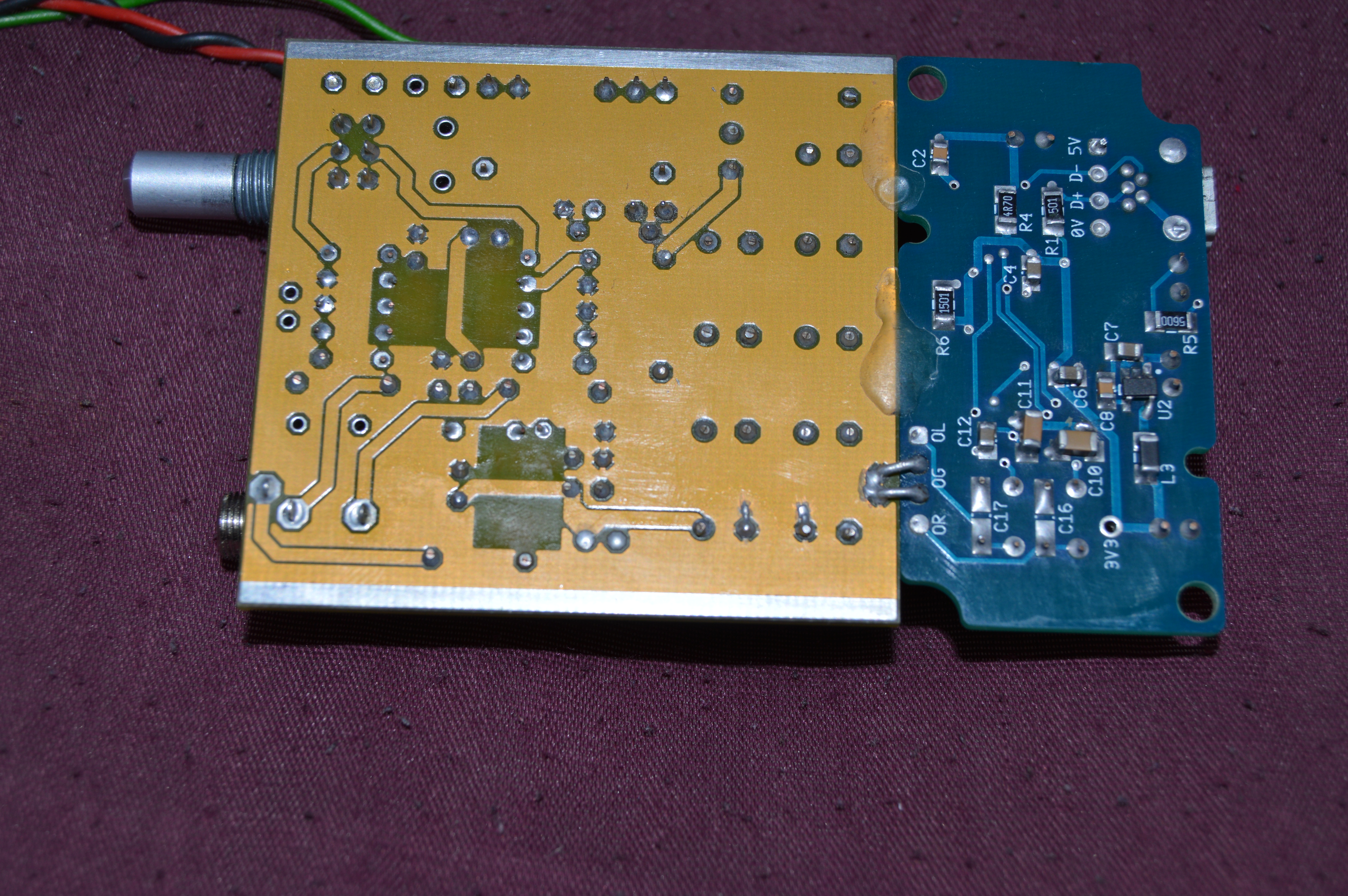
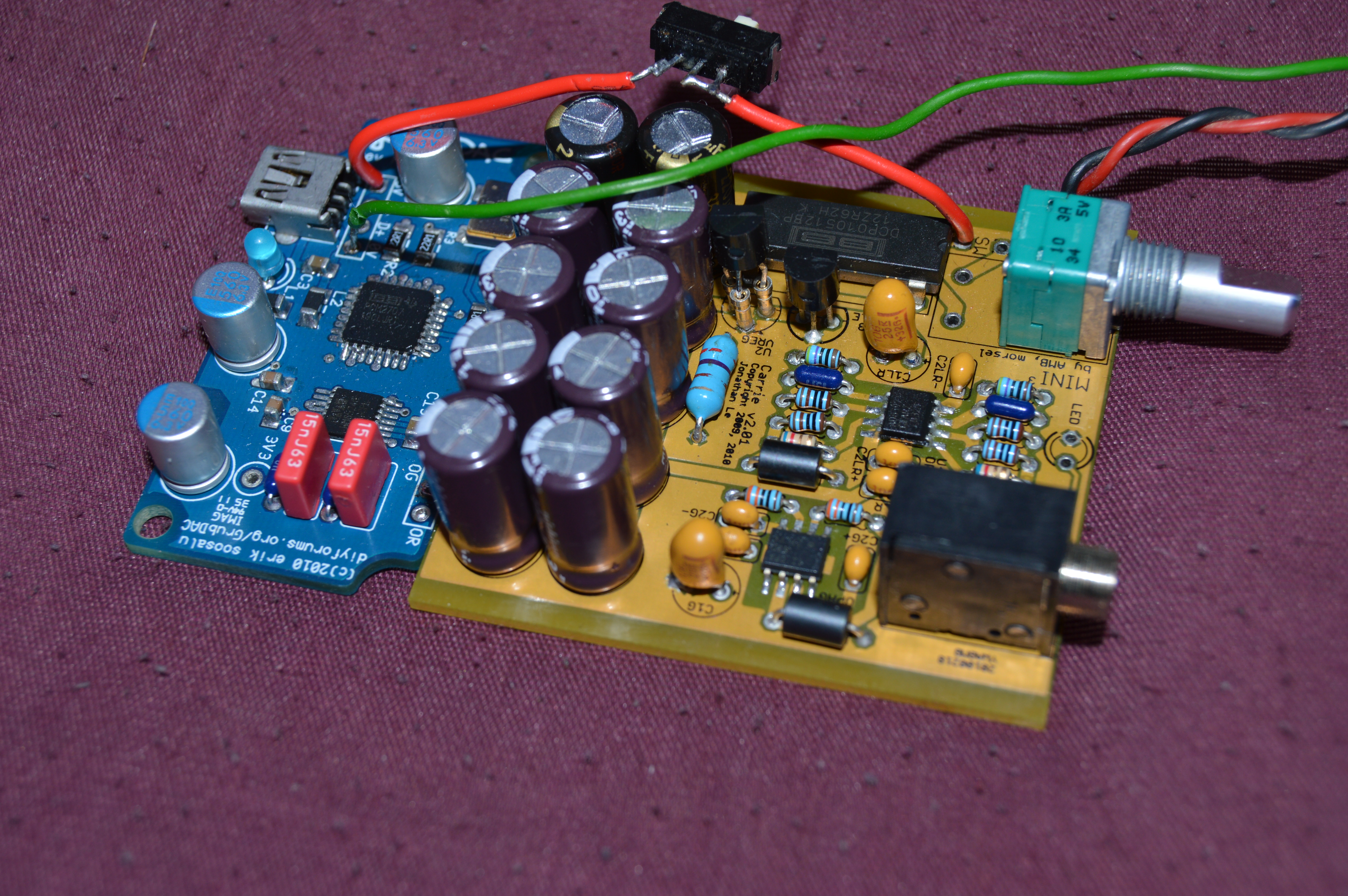
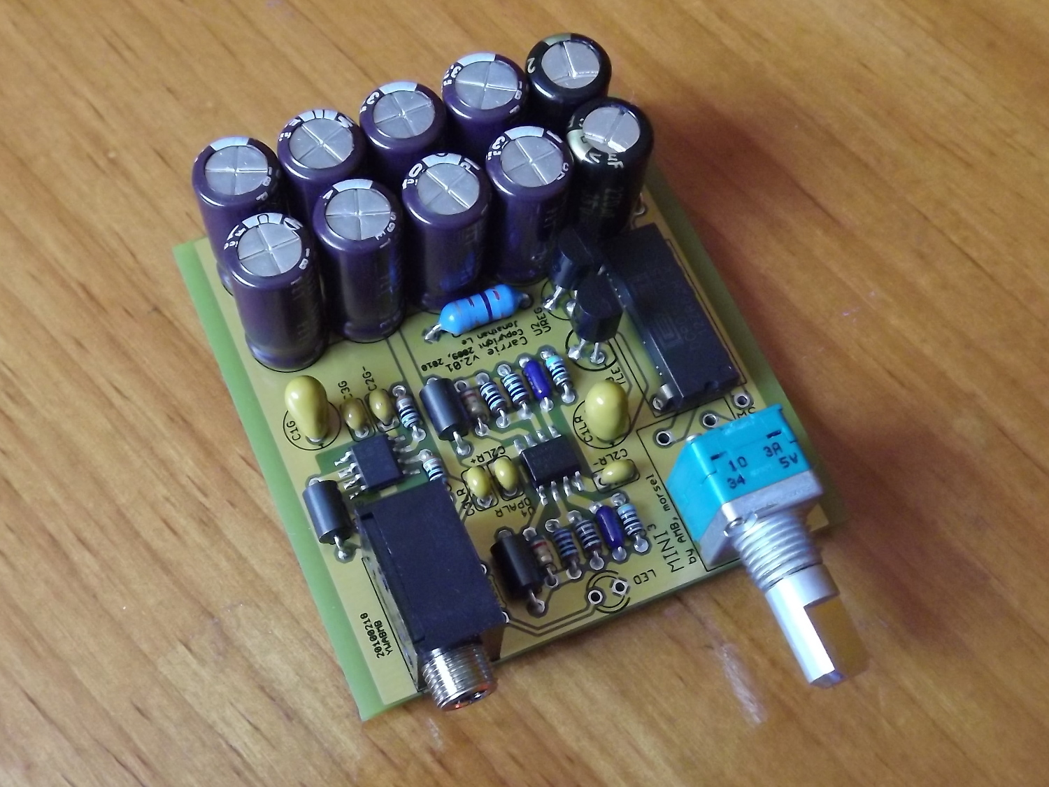
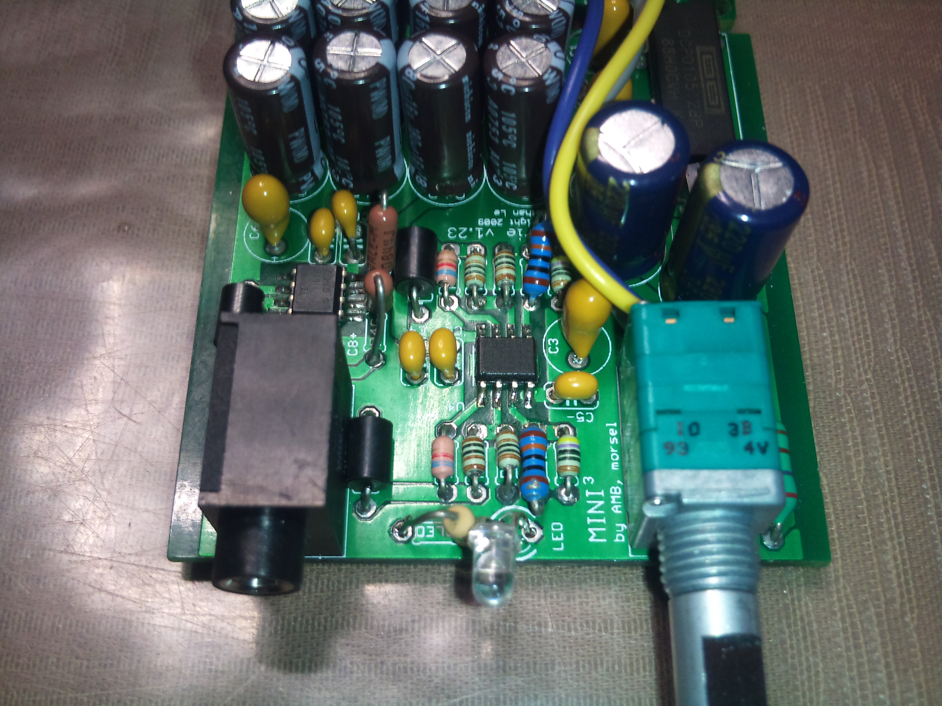
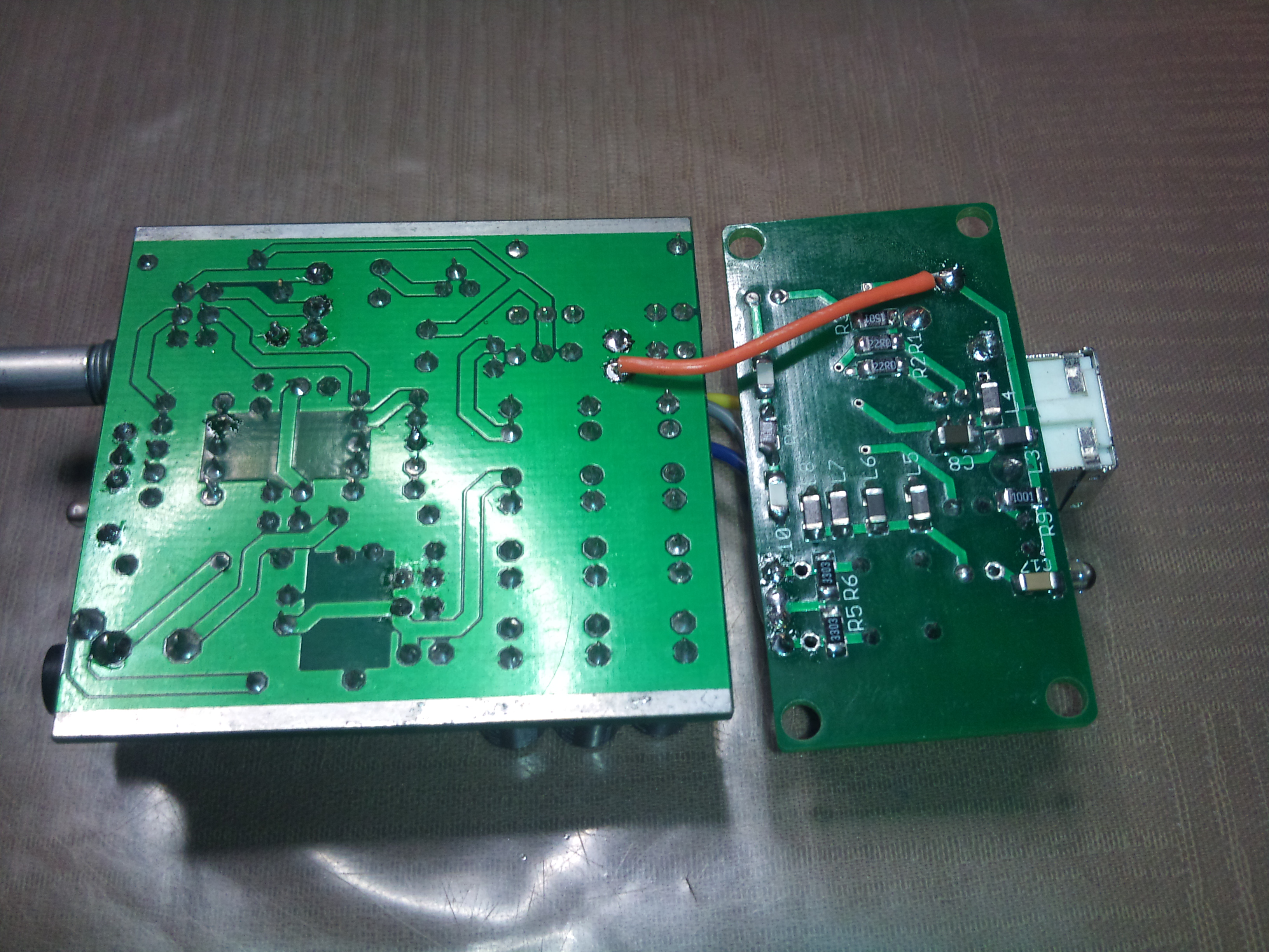
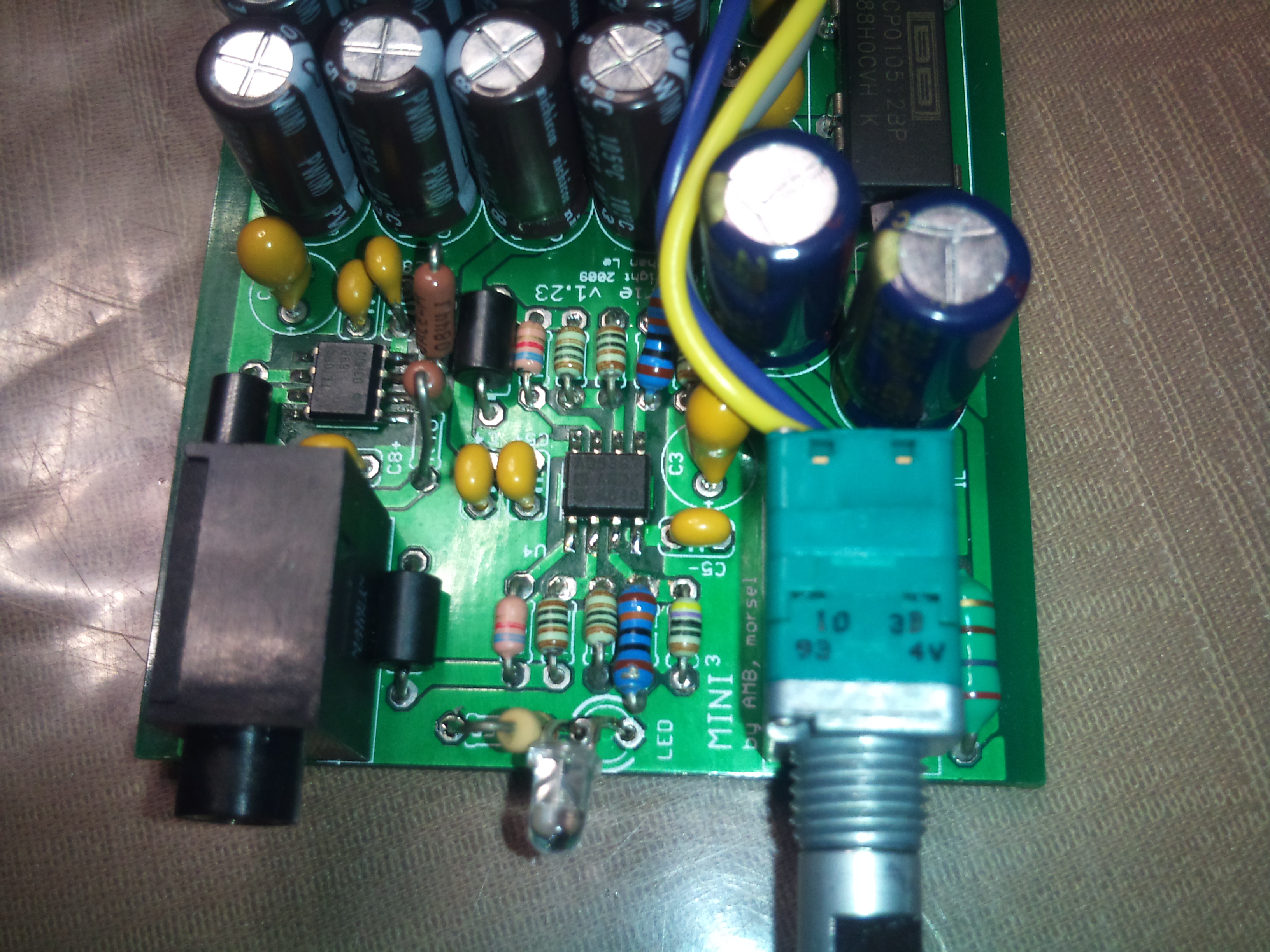
I was noticing some distortion as volume increased, and the power LED for the Carrie amp would come on when I turned it on but fade off within a few seconds, so I opened it up to take a look. I noticed that if I touched certain areas on the bottom of the PCB (where the through-hole leads were soldered), particularly around the potentiometer and DC/DC converter, I could get the distortion to stop and the sound quality to improve, and the LED would light back up. I figured that the DC/DC converter was shot, so I ordered a new one and changed it out. It didn't help, and the new converter is getting really hot for some reason. I've checked to make sure I'm getting 5V DC incoming power (I am), and I checked to make sure I have the proper DC/DC converter (15V) with the corresponding voltage regulator (12V), which is right. I'm all out of ideas here. I hate to think about tossing it since it was a great little combo, and I'm not sure there's anything on the market to fill that niche without spending a lot of money. Anyone have any ideas as to what might have happened?
 
Jan 23, 2014 at 8:20 PM Post #865 of 913
TBomb06, the first thing that comes to mind is a cold solder joint. I'd try reflowing stuff around the sensitive area, going as far as reflowing the whole board.
 
 
Today I finally got around to beginning this project. I had never soldered SMDs before so I started with assembling the DAC. That way if I broke or lost something I would order it with the parts for the amp.
 
Turns out it was a lot easier than I feared. With the fine tip of my iron I was able to solder the ICs pin by pin, which was a nice surprise. I expected the board to take a few days to assemble but I did it in a few hours. Quite a fun project, so far.
 
I haven't powered it yet since I washed it with flux cleaner. I'll wait for tomorrow to make sure everything is dry. Fingers crossed.
 
Crappy cellphone pictures:


Now, reading the BOM I see we are given the choice between a 12v rail and a 10v one. I figure the advantage of the 10 V is more current, but I can't really see the advantage of more voltage. On what factors should I make my decision? 
 
Feb 10, 2014 at 10:17 PM Post #867 of 913
Hi guys.
 
So I spent the day going trough the BOM, trying to find everything I need from a single supplier.
 
The BOM lists a part # for the output jack for Digikey only : http://www.digikey.com/product-detail/en/SJ1-3533NG/CP1-3533NG-ND/738701
 
Searching on Mouser, I found a part that I believe would fit on the board nicely. The measurements are not perfect, but it's close enough that it would fit with some hacking, at the worst. Can anyone give me a second opinion on this, in case I am missing something? Here's the part I found : http://ca.mouser.com/ProductDetail/Kycon/STX-3150-3C/?qs=sGAEpiMZZMv0W4pxf2HiV3p8sCuGBLyboz2QM3ee%2fdo%3d
 
Feb 10, 2014 at 11:55 PM Post #868 of 913
Well, I went ahead and ordered everything from Mouser, including the jack I found. For anyone interested, here's my BOM : http://www.mouser.com/ProjectManager/ProjectDetail.aspx?AccessID=02dba010a7
 
It includes the 12V converter and 10V regulator, along with resistors for gains of 2 and 3. I also selected a non-switching volume pot to have more control. It's not exactly the same parts as in the official BOM as some parts were out of life and some back order. I found replacements.
 
The official BOM lists no part # for U4 at mouser, but it is included in my BOM. They started stocking this chip recently. With this, I was able to avoid placing a second order at Digikey and order everything from Mouser.
 
Getting excited to get this little guy running. 
k701smile.gif

 
Feb 11, 2014 at 12:22 AM Post #869 of 913
  Now, reading the BOM I see we are given the choice between a 12v rail and a 10v one. I figure the advantage of the 10 V is more current, but I can't really see the advantage of more voltage. On what factors should I make my decision? 

12V will give more volt swing at the cost of slightly higher power use. I'd say it's only about 3dB headroom either way.
So, for headphones under 100 ohm go 10V, headphones over 100 ohm go 12V if you think you would like to, or need to, maximize headroom.
 
As for the jacks, the mouser one does look close enough to me too. With round holes and flat pins, that 0.15mm difference front-to-back should be fine. Flat pins won't bent side to side, but the hole spacing is spot on in that direction.
 
Feb 19, 2014 at 5:11 PM Post #870 of 913
I received my Mouser order and the first thing I checked was if the jack fitted. It fits in perfectly without bending anything. In fact the holes are so large in the PCB the jack fit loosely in with place to move around.
 
So with that and the fact Mouser started stocking U4, it's now possible to order the whole BOM from Mouser.
 

Users who are viewing this thread

Back
Top