


joneeboi
Headphoneus Supremus
- Joined
- Jul 7, 2006
- Posts
- 1,919
- Likes
- 20
A guy takes a year and half hiatus and you go ahead and change everything on him? 
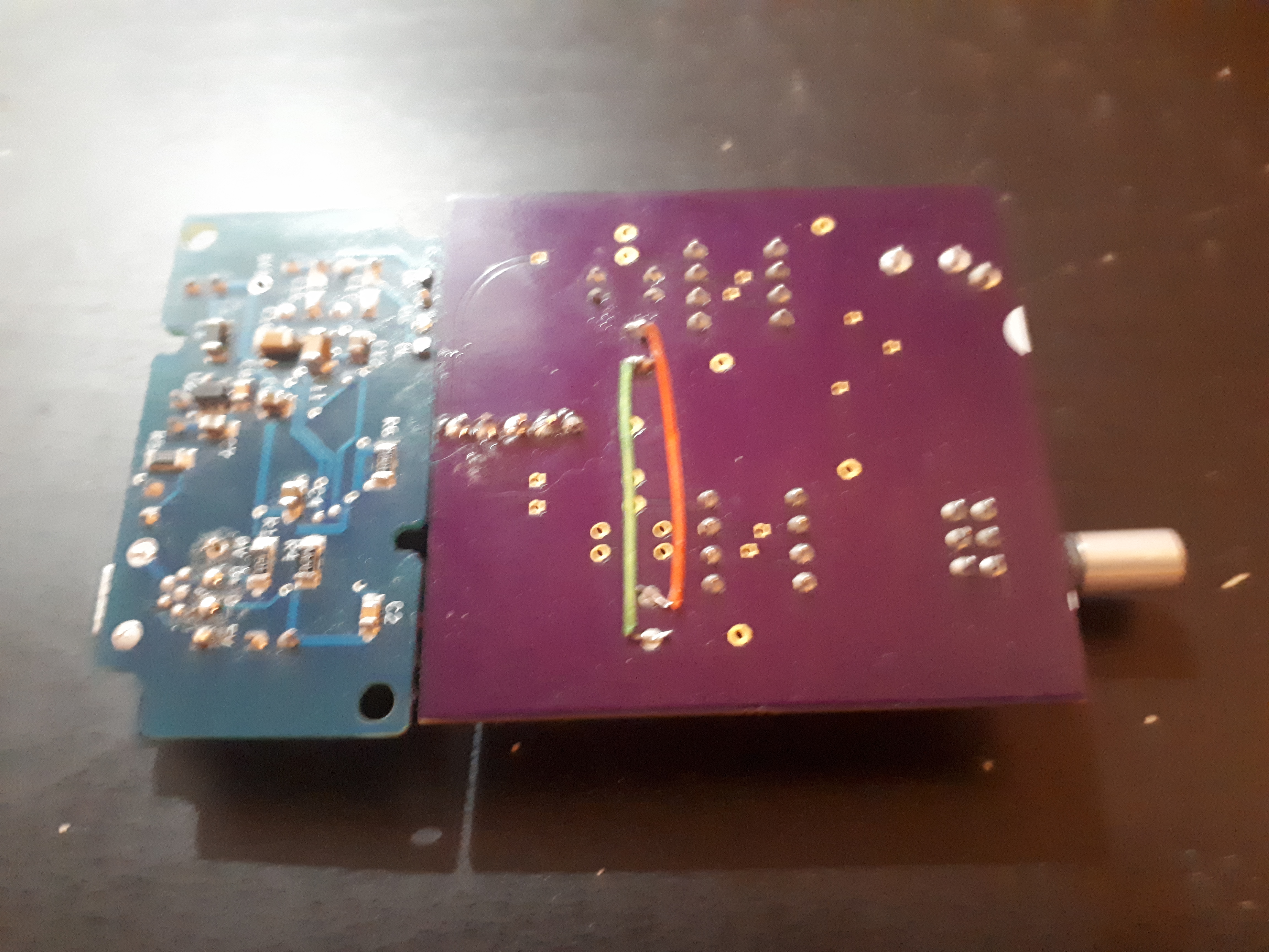
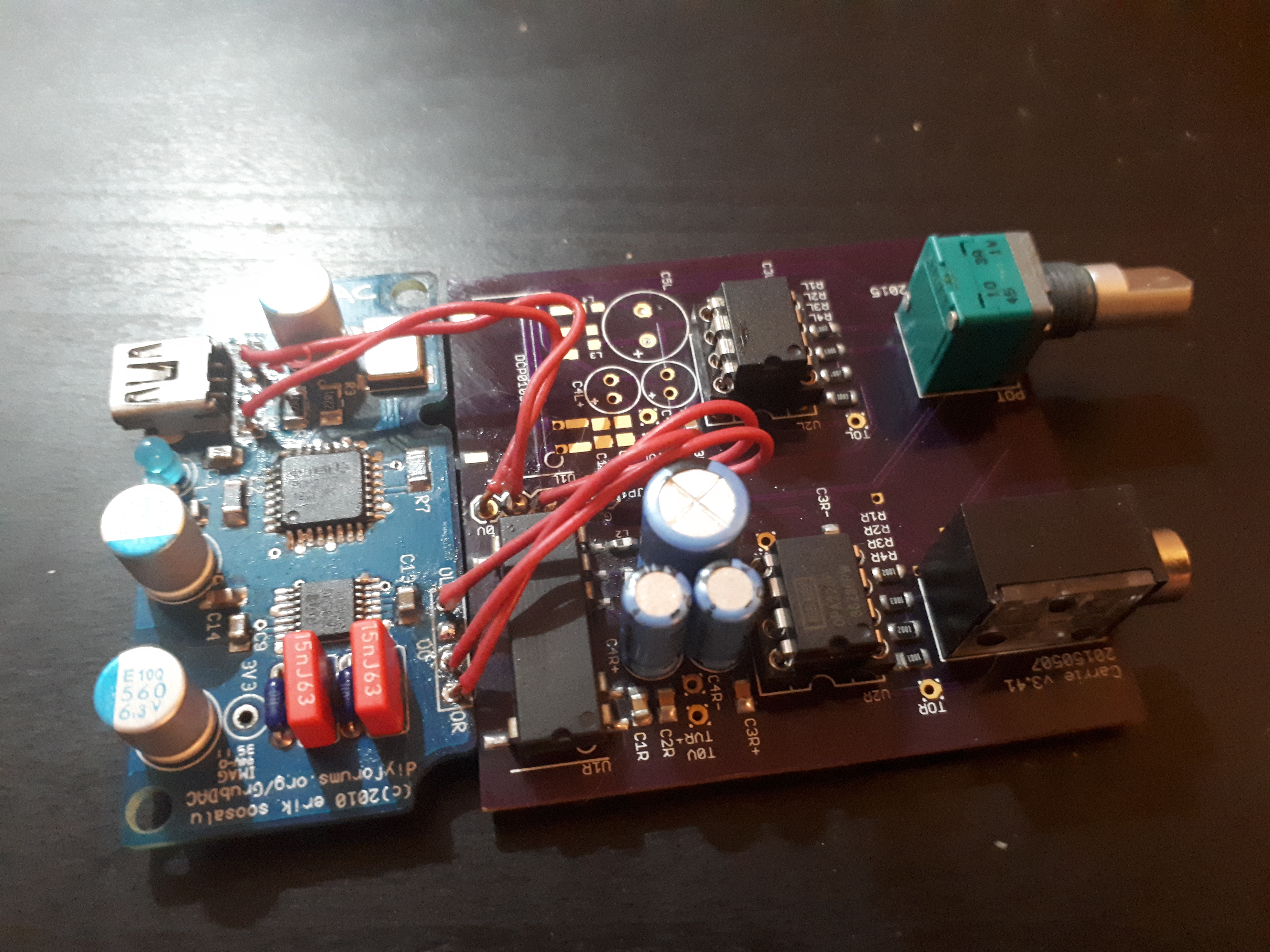
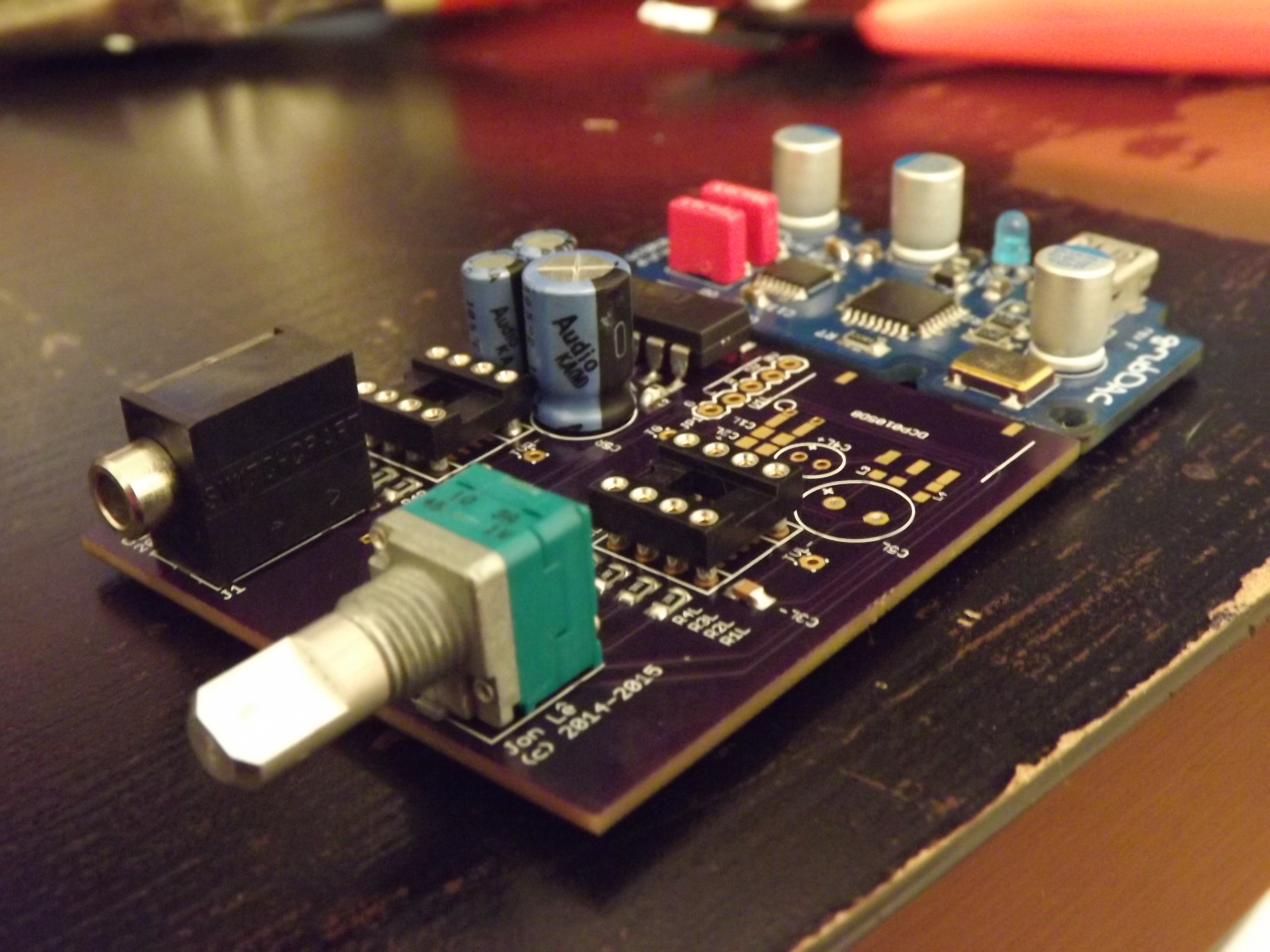
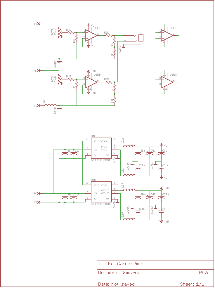
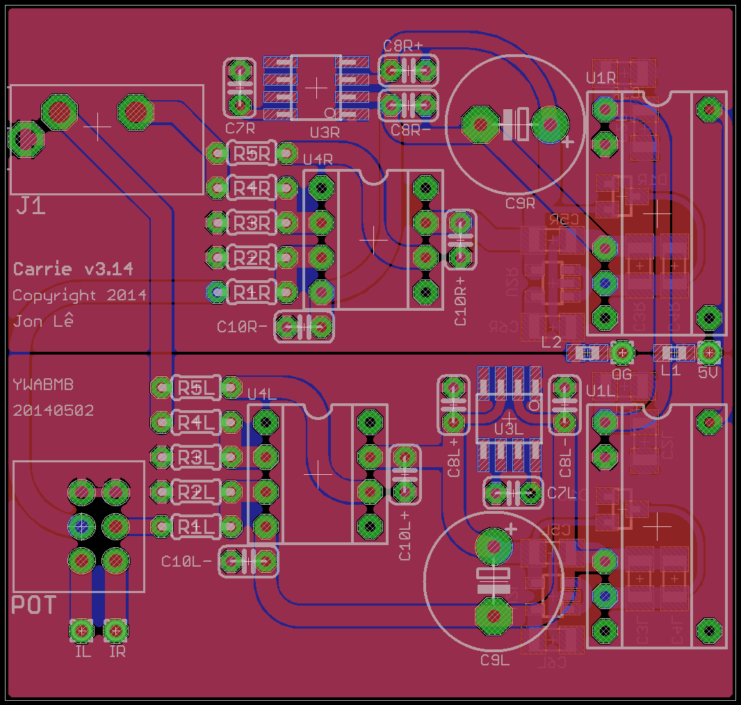
Presenting the Carrie Amp v3.


Yes, I'm back, and I've been silently toiling away on a new design for the past few weeks. Wow, it's great to see so many new and exciting projects here on head-fi; the DoodleBug seems relevant. Carrie Amp v2 was a great success for me, seeing where a little ingenuity and a lot of hard work could go. Now I'm back with another product, a new approach to the same problem.
This product essentially boils down to what I'd like to use at work. The original Carrie was made for my days at university, studying in a loud area with my laptop's broken headphone out jack. Now, it's being used for my cubicle-dwelling job as an engineer, where I sit all day and listen to music. (Office Space is starting to lose its humour as it approaches my reality.) I'm not paying tons of attention to what I'm listening to, so it's not the worst thing in the world if there's no audible difference. The world of computer ground noise is deep and mysterious, so we'll see how this bad boy performs out in the wild.
Some highlights of the design:
- Separate power supplies and grounds as much as possible. With the potentiometer and output jack/termination style, I don't really have much of a choice here. Let's see where the limit of the noise and intereference is, especially with a full-on solution like the DoodleBug. This will allow some side by side listening tests with a Carrie Amp v2 with its Mini^3 amplifier circuit. This duality also doubles the component cost, but a person could conceivably populate one power supply and jumper it to the other channel.
- Dual single CMoy design with rollable opamps. Carrie Amp v3 is my learning vehicle (school bus?) in power supply and PCB design. I want to have a great sound for my 650s and SR60s, but I'm not sure yet which opamps will get me there.
- Through-hole components where possible for easier build.
- Lowest noise components where possible, eg. TLE2426 SO8 package, LP2985-10 VREG with bypass capacitor.
- Still the same board size for compatibility with the DACs you know and love, ie. bantamDAC, GrubDAC, and SkeletonDAC.
You may notice some changes/oddities about the design as well.
- Two single-channels instead of three. I'll admit, I got caught up in the O2 Amp hullabaloo, and it got me thinking about the circuit design. In the discussion, it came up that crosstalk could only be mitigated by fully separate and bipolar power supplies and proper grounding. Any non-flamey input on this matter would be greatly appreciated.
- Not symmetrical design. This could lead to weird imbalances between channels in impedances and interference. Will it sound different? Let's find out.
- Connected input ground of U1 with the output ground. I know this seems like taking two steps forward and anywhere from one to ten steps back in terms of noise mitigation. This seems necessary to creating a +/- 5 V power supply, though I haven't tested if the output voltage would float away otherwise. Yay for prototyping.
Still to do:
- Fix TLE bypass cap connection
- Add back VALUE layer for U1 and U3
- Add SO8 opamp underneath U4 a la PIMETA v2. Requires rerouting VR- to C10R-.
- Reposition components to not cut off ground plane
- Add LED to the board
- Move output jack and potentiometer before final FPE plate design
- Finalize BOM
This is still in the prototyping stage, so I need nine volunteers to help me test this sucker. These are the problems I hope to answer in the prototyping stage:
- Will the output ground provide adequate current? I plan on manufacturing the boards with 4 oz. copper, but just from the looks of the layout, it seems grossly imbalanced towards the right channel in terms of signal pollution. Do I rip it all up and go with a star ground?
- What kind of noise can we expect from the DAC's output ground? Does a person need to simply stick a DoodleBug in the signal path and simplify the rest?
- What is the difference in audible and measurable noise between using one power supply and two?
- See how difficult it is to solder the SMD portion is around U1's output portion.
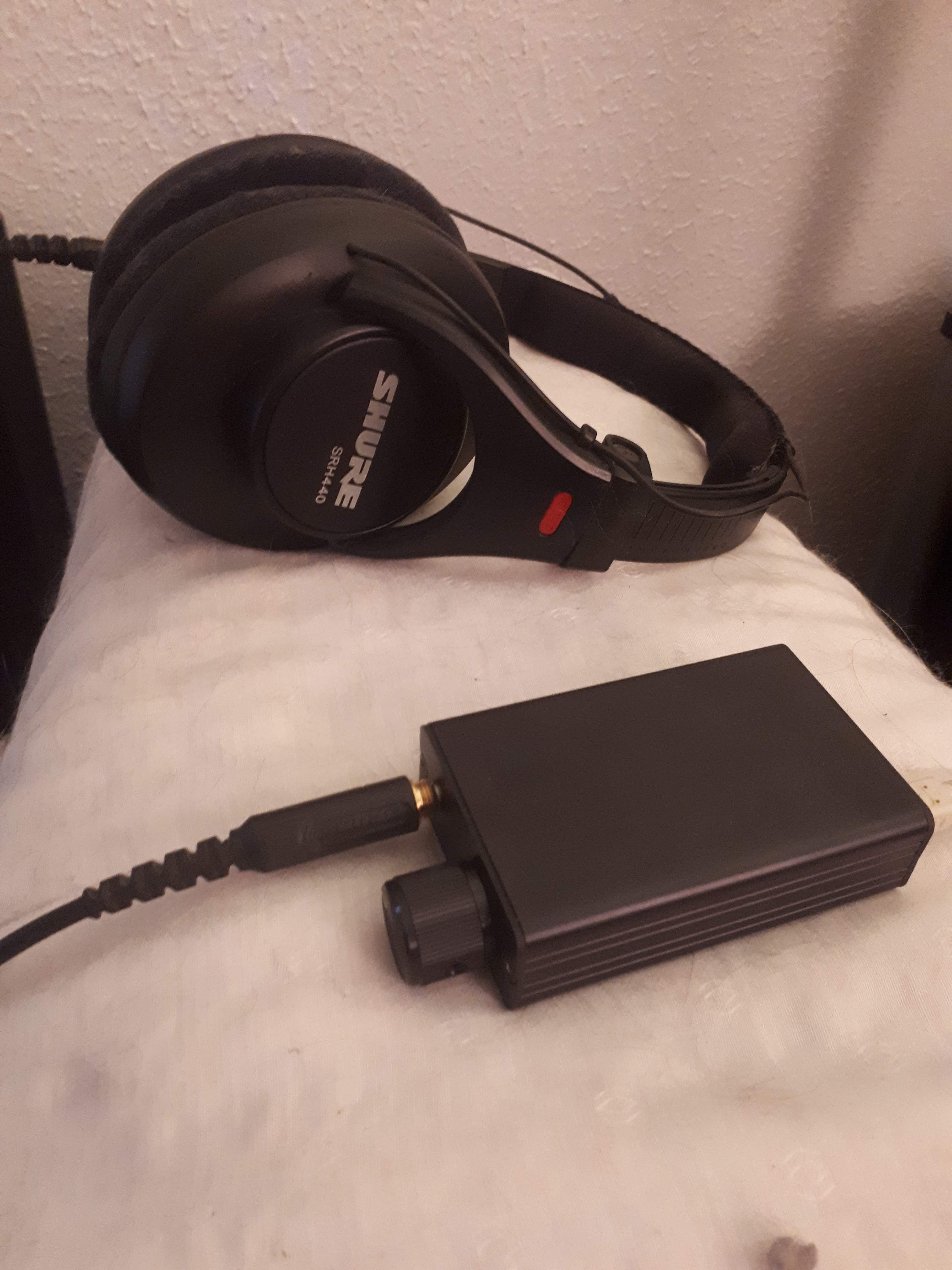
- Find which opamps work best with 650s and SR60s
Discussion
In my design, I see two competing ideologies: "just listening" and aiming for purity of electrical design. The classic "fun vs. accurate" dynamic, convenient vs. objective. For the past year and a half, I've been playing in the fun side of the arena.
Where have I been all this time? Just listening to music. I'm horrible for relistening to the same song ad infinitum (Clarity by Zedd is on repeat one in my car), so I spent the time exploring new styles and services. I have iTunes Match and Rdio, which have made music discovery much easier. I used to listen to WAVs, and now I stream 320 kbps. It's not the gold standard of audiophilia, but I've stopped listening to the equipment in favour of the music. I got my 650s almost two years ago, and they've enabled me to stop imagining audible changes and listen. My modded SR60s balance out the audio equation with the help of my PortaPros for my walk to and from work. I equalize my car stereo for extra bass boost, and I love the sound of my EarPods on my iPhone. I bought a Pioneer A4 for AirPlaying from the iPhones, iPads, and MacBooks in our home (dat subwoofer), and my two bookshelf speakers in the home theater cover the other end of the home when AirPlaying to the Apple TV 2 or XBMC on the Raspberry Pi. I live in a 500 sq. ft. studio, so it's not hard to reach our music.
Sounds pretty rosy, eh? So why am I back? I'm bouncing back and forth between fun and accurate because I learned that each leads to the other. I did the portable battery powered amp via line out dock thing, both on the Creative Zen Vision:M and iPod ecosystems, and I did the diyMod thing. I organized meets, rolled some opamps in higher fidelity amplifiers I built, and openly scorned low quality audio online and to friends. After a while, I kinda got sick of it all, and then I just listened to my music. Now I'm bored of that, and the pendulum is swinging back towards accuracy.
The design isn't perfect. I'm still learning, and this is still the prototype stage. I'd love to get some feedback from all the much more talented designers and builders here at head-fi. (That's you!) It's a hypothesis, so please let me know if there are any glaring oversights or areas of improvement.
tl;dr New design. Need nine prototypers.
Presenting the Carrie Amp v3.
Yes, I'm back, and I've been silently toiling away on a new design for the past few weeks. Wow, it's great to see so many new and exciting projects here on head-fi; the DoodleBug seems relevant. Carrie Amp v2 was a great success for me, seeing where a little ingenuity and a lot of hard work could go. Now I'm back with another product, a new approach to the same problem.
This product essentially boils down to what I'd like to use at work. The original Carrie was made for my days at university, studying in a loud area with my laptop's broken headphone out jack. Now, it's being used for my cubicle-dwelling job as an engineer, where I sit all day and listen to music. (Office Space is starting to lose its humour as it approaches my reality.) I'm not paying tons of attention to what I'm listening to, so it's not the worst thing in the world if there's no audible difference. The world of computer ground noise is deep and mysterious, so we'll see how this bad boy performs out in the wild.
Some highlights of the design:
- Separate power supplies and grounds as much as possible. With the potentiometer and output jack/termination style, I don't really have much of a choice here. Let's see where the limit of the noise and intereference is, especially with a full-on solution like the DoodleBug. This will allow some side by side listening tests with a Carrie Amp v2 with its Mini^3 amplifier circuit. This duality also doubles the component cost, but a person could conceivably populate one power supply and jumper it to the other channel.
- Dual single CMoy design with rollable opamps. Carrie Amp v3 is my learning vehicle (school bus?) in power supply and PCB design. I want to have a great sound for my 650s and SR60s, but I'm not sure yet which opamps will get me there.
- Through-hole components where possible for easier build.
- Lowest noise components where possible, eg. TLE2426 SO8 package, LP2985-10 VREG with bypass capacitor.
- Still the same board size for compatibility with the DACs you know and love, ie. bantamDAC, GrubDAC, and SkeletonDAC.
You may notice some changes/oddities about the design as well.
- Two single-channels instead of three. I'll admit, I got caught up in the O2 Amp hullabaloo, and it got me thinking about the circuit design. In the discussion, it came up that crosstalk could only be mitigated by fully separate and bipolar power supplies and proper grounding. Any non-flamey input on this matter would be greatly appreciated.
- Not symmetrical design. This could lead to weird imbalances between channels in impedances and interference. Will it sound different? Let's find out.
- Connected input ground of U1 with the output ground. I know this seems like taking two steps forward and anywhere from one to ten steps back in terms of noise mitigation. This seems necessary to creating a +/- 5 V power supply, though I haven't tested if the output voltage would float away otherwise. Yay for prototyping.
Still to do:
- Fix TLE bypass cap connection
- Add back VALUE layer for U1 and U3
- Add SO8 opamp underneath U4 a la PIMETA v2. Requires rerouting VR- to C10R-.
- Reposition components to not cut off ground plane
- Add LED to the board
- Move output jack and potentiometer before final FPE plate design
- Finalize BOM
This is still in the prototyping stage, so I need nine volunteers to help me test this sucker. These are the problems I hope to answer in the prototyping stage:
- Will the output ground provide adequate current? I plan on manufacturing the boards with 4 oz. copper, but just from the looks of the layout, it seems grossly imbalanced towards the right channel in terms of signal pollution. Do I rip it all up and go with a star ground?
- What kind of noise can we expect from the DAC's output ground? Does a person need to simply stick a DoodleBug in the signal path and simplify the rest?
- What is the difference in audible and measurable noise between using one power supply and two?
- See how difficult it is to solder the SMD portion is around U1's output portion.
- Find which opamps work best with 650s and SR60s
Discussion
In my design, I see two competing ideologies: "just listening" and aiming for purity of electrical design. The classic "fun vs. accurate" dynamic, convenient vs. objective. For the past year and a half, I've been playing in the fun side of the arena.
Where have I been all this time? Just listening to music. I'm horrible for relistening to the same song ad infinitum (Clarity by Zedd is on repeat one in my car), so I spent the time exploring new styles and services. I have iTunes Match and Rdio, which have made music discovery much easier. I used to listen to WAVs, and now I stream 320 kbps. It's not the gold standard of audiophilia, but I've stopped listening to the equipment in favour of the music. I got my 650s almost two years ago, and they've enabled me to stop imagining audible changes and listen. My modded SR60s balance out the audio equation with the help of my PortaPros for my walk to and from work. I equalize my car stereo for extra bass boost, and I love the sound of my EarPods on my iPhone. I bought a Pioneer A4 for AirPlaying from the iPhones, iPads, and MacBooks in our home (dat subwoofer), and my two bookshelf speakers in the home theater cover the other end of the home when AirPlaying to the Apple TV 2 or XBMC on the Raspberry Pi. I live in a 500 sq. ft. studio, so it's not hard to reach our music.
Sounds pretty rosy, eh? So why am I back? I'm bouncing back and forth between fun and accurate because I learned that each leads to the other. I did the portable battery powered amp via line out dock thing, both on the Creative Zen Vision:M and iPod ecosystems, and I did the diyMod thing. I organized meets, rolled some opamps in higher fidelity amplifiers I built, and openly scorned low quality audio online and to friends. After a while, I kinda got sick of it all, and then I just listened to my music. Now I'm bored of that, and the pendulum is swinging back towards accuracy.
The design isn't perfect. I'm still learning, and this is still the prototype stage. I'd love to get some feedback from all the much more talented designers and builders here at head-fi. (That's you!) It's a hypothesis, so please let me know if there are any glaring oversights or areas of improvement.
tl;dr New design. Need nine prototypers.

