Capacitor Upgrades
Oct 1, 2013 at 1:19 AM Thread Starter Post #1 of 22

HPiper

Headphoneus Supremus
Joined
Jan 28, 2012
Posts
1,717
Likes
147
I see a lot of people saying that they upgraded the capacitors on their amp and gotten better sound. What does one capacitor do better than another (of the same value) that results in better sound. If you were looking to upgrade a given capacitor how would you know that any given capacitor was going to be better than what you already have?
 
Feb 12, 2014 at 5:06 PM Post #2 of 22
There can be many advantages depending on the ratings of the stock resistor. Based on the mistakes of the circuit designer, one can gain a lot from changing the capacitor. Since you can’t change the value of the capacitor, what one can change is the voltage rating of the capacitor. Higher the voltage rating of the capacitor, the more voltage it can produce at the output efficiently without any issues. The second thing that be improved is the tolerance of the capacitor, you’ll have to buy a bit more expensive capacitor but it’ll give you a better result for sure. 

 
Feb 13, 2014 at 5:03 PM Post #3 of 22
It really depends on what the cap is there for. For power supply filtering, you're looking for low ESR ratings, and generally, the bigger the better (in terms of capacitance - farads), while keeping at least the rated voltage.
 
For signal coupling caps, there is a huge difference between capacitor types (electrolytic vs film is a pretty drastic change), and there are tons of "audiophile" capacitors out there. Signal caps are generally the first to "upgrade".
 
Feb 13, 2014 at 8:59 PM Post #4 of 22
  It really depends on what the cap is there for. For power supply filtering, you're looking for low ESR ratings, and generally, the bigger the better (in terms of capacitance - farads), while keeping at least the rated voltage.
 
For signal coupling caps, there is a huge difference between capacitor types (electrolytic vs film is a pretty drastic change), and there are tons of "audiophile" capacitors out there. Signal caps are generally the first to "upgrade".


^ this.
 
Also, you may have read remarks from people restoring vintage equipment.  Unfortunately, electrolytic capacitors have a finite lifetime.  There's a fluid between layers of dielectric rolled up inside the "can."  That fluid evaporates over time and even quicker when in use (we're talking decades, perhaps, though).  So, the first thing you often hear when someone is looking to restore a vintage piece of audiophile gear is "re-capping."
 
Feb 13, 2014 at 9:56 PM Post #5 of 22
If you were looking to upgrade a given capacitor how would you know that any given capacitor was going to be better than what you already have?


Good question.

The short answer is that there is no easy way of telling if the change you have made is an improvement, even after you have made it.

There might be a measurable improvement in distortion. Got an accurate distortion meter?

There might be an audible change. Got a second unmodified amp for side-by-side comparison? How you gonna tell if the change is for the better? Got an expert listening panel handy?

There are many different types of capacitors. It takes time to become familiar with their characteristics. There are places in circuits where caps are more or less likely to affect the sound. Know which are which?

Guys like to frig around with things, they like to be thought of as experts. Change a cap or two, probably you didn't break anything, you can claim you've made a big improvement, who can prove any different?

w
 
Feb 13, 2014 at 10:13 PM Post #6 of 22
 
There can be many advantages depending on the ratings of the stock resistor. Based on the mistakes of the circuit designer, one can gain a lot from changing the capacitor. Since you can’t change the value of the capacitor, what one can change is the voltage rating of the capacitor. Higher the voltage rating of the capacitor, the more voltage it can produce at the output efficiently without any issues. The second thing that be improved is the tolerance of the capacitor, you’ll have to buy a bit more expensive capacitor but it’ll give you a better result for sure. 

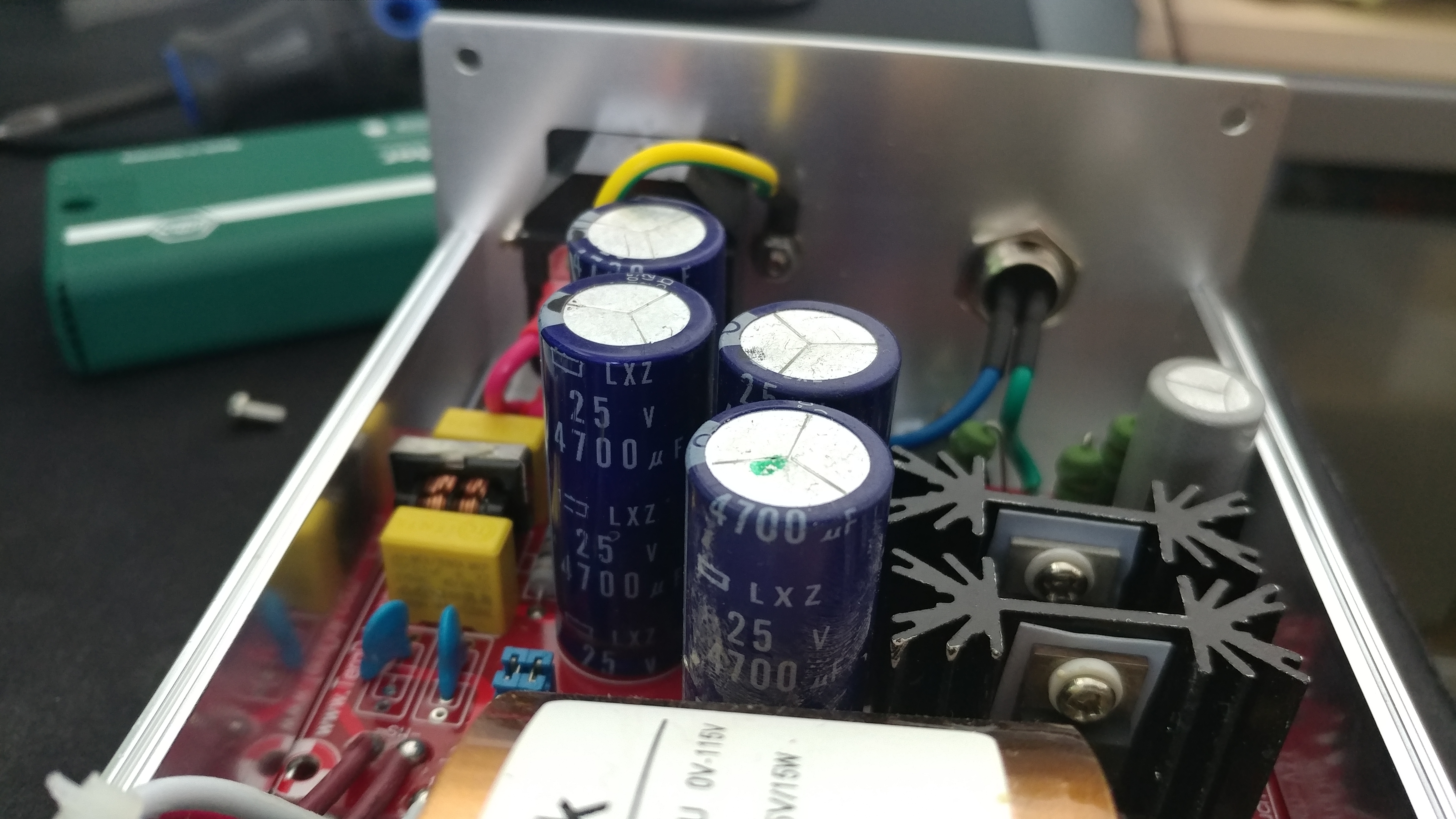
This is false in regards to voltage rating. The voltage rating is what the capacitor can handle. Let's assume a transformer secondary = 32VAC We simply multiply this by the square root of 2 (approx. 1.4142) Therefore, Working Voltage WV = 32VAC X 1.4142 = 45.25V. Thus, you want to use the next higher rating, which is 50v rating.
 
Now, when looking for a quality capacitor, you typically want the lowest ESR, along with the highest ripple rating that you can get within your size dimension. Capacitor uf values differ in their applications,  but for a power supply section, the more the better. Cost has really dropped the past decade, so diminishing returns isn't such a big issue anymore.
 
Tolerance is primarily when you're dealing with sensitive applications like precise filters and crossovers. However, film caps are typically much better than electrolytics if you have the physical space and funds for them.
 
Cheers,
Brunk
 
Feb 25, 2014 at 8:30 AM Post #8 of 22
 
^ this.
 
Also, you may have read remarks from people restoring vintage equipment.  Unfortunately, electrolytic capacitors have a finite lifetime.  There's a fluid between layers of dielectric rolled up inside the "can."  That fluid evaporates over time and even quicker when in use (we're talking decades, perhaps, though).  So, the first thing you often hear when someone is looking to restore a vintage piece of audiophile gear is "re-capping."

Indeed, and even the better quality ones dry out.
 
I took apart a Marantz CD60 last year, which had finally reached the end of its economically serviceable life after 23 years and many repairs.
 
The main power supply caps were Elna (one of the better audio quality capacitor brands), and I disassembled one (carefully, the electrolyte may contain toxic components).  The paper separator was fairly dry and covered in patches of brown crystallized electrolyte.
 
Feb 25, 2014 at 9:03 AM Post #9 of 22
  Tolerance is primarily when you're dealing with sensitive applications like precise filters and crossovers. However, film caps are typically much better than electrolytics if you have the physical space and funds for them.
 
Cheers,
Brunk

Yup
 
You will rarely find electrolytic capacitors used where tolerance is of importance.  Your typical electrolytic cap has a capacitance tolerance of 20% (even expensive audio-graded ones), some 10%.
 
This has one advantage; if you are replacing electrolytic caps the exact capacitance <probably> doesn't matter too much.  Not all capacitance values in all voltage ratings of the type you are looking for are always available.  Often you can get away with the nearest one (just  make sure you use at least the appropriate minimum voltage rating though).
 
Most manufacturers optimise the components they use not only on value/rating, but also on cost of mechanised placement on the PCB prior to soldering.  Thus if ideally a 33microFarad 25V cap would be called for, but the board is already populated by a load of 47microFarad 25V ones, the manufacturer may simply opt to use another 47microfarad one instead, if that saves having to use any 33microFarad/25V ones at all.  The same applies to a smaller degree to resistors, transistors etc, wherever the exact rating of the component matter less. Cheaper to make that way.
 
This is one reason niche high-end audio equipment ends up being more expensive.  There they usually DO use the optimal value component from an audio engineering perspective, even if that means a marginal increase in production cost.  And if they are entirely hand-built, there is no need to reduce the variety of componens to minimise the cost of the production run.
 
Nov 25, 2019 at 5:47 PM Post #10 of 22
I thought this could be a decent place to post my concern. I'm planning to change out the capacitors here in my Teradak linear power supply and was wondering if the following picture of Nichicon caps would work with it!

Also, before I start un-soldering all of the wires is there any precautions I should take, in terms of order of what should be unsoldered/soldered on and off first and last?
1125191415.jpg
NICHICON-76217.jpg
 
Last edited:
Nov 25, 2019 at 9:24 PM Post #11 of 22
I thought this could be a decent place to post my concern. I'm planning to change out the capacitors here in my Teradak linear power supply and was wondering if the following picture of Nichicon caps would work with it!

Also, before I start un-soldering all of the wires is there any precautions I should take, in terms of order of what should be unsoldered/soldered on and off first and last?

NICHICON-76217.jpg

You responded to an old thread, and it's usually best to start your own thread when it isn't entirely related.

However, if you take a picture of the caps on the supply now, I'm sure I (or somebody else on here) can tell you if they are alright. I'm not sure what caps they used, and you should at least match the voltage and capacitance that they used.

In terms of order, obviously make sure it's unplugged (and probably unplugged for a few minutes to be safe). If the caps are drained, it doesn't really matter which order you go on.
 
Nov 25, 2019 at 9:57 PM Post #12 of 22
@DutchGFX Thank you. I was planning to start a thread in hopes of others benefiting from the information and experience.

Definitely going to make sure the caps are drained as recommended, and matching the voltage. I was reading it can be good to have more uF? If you can fit it in place...

Will make a nrw thread, though. :)
 
Nov 26, 2019 at 2:19 PM Post #13 of 22
@DutchGFX Thank you. I was planning to start a thread in hopes of others benefiting from the information and experience.

Definitely going to make sure the caps are drained as recommended, and matching the voltage. I was reading it can be good to have more uF? If you can fit it in place...

Will make a nrw thread, though. :)

Yeah if you increase the capacitance you will reduce your power supply ripple. Depending on the topology of the amplifier this might not matter that much but if it's single ended then it would likely be beneficial. Unclear how much it would help tho, but generally if you can have bigger decoupling caps it is wise to do so
 
Nov 27, 2019 at 8:34 AM Post #14 of 22
I thought this could be a decent place to post my concern. I'm planning to change out the capacitors here in my Teradak linear power supply and was wondering if the following picture of Nichicon caps would work with it!

Also, before I start un-soldering all of the wires is there any precautions I should take, in terms of order of what should be unsoldered/soldered on and off first and last?

NICHICON-76217.jpg

You might try just removing the four screws on the PCB, first. Then see if there's enough slack in the wiring to flip it over. If so, you might be able to remove and replace those caps without ever de-soldering the wiring. No reason to make more work for yourself if there's another way. :wink:

As for the caps, I confess that I'm not familiar with that "color" Nichicon. It might help if you had photographed the letter codes of the type of cap, not the ratings. Nichicon UHE and UPW are generally the best power caps, but UHEs are more or less black and UPWs are sort of a purplish-brown. I'm not saying that they haven't created some nifty new range of power caps, but I'm not aware of it. In lower voltages such as for DACs, they make new types of super-power caps all the time. Not so much in the 1000uf 35V range.

My personal preference is still for Panasonic FM in that rating, but UHE can be better in some physical sizes and electrical ratings. It all depends on the specific cap.

One last thing - before taking any of this apart, I would strongly recommend that you have a clear understanding of that trimmer pot, what it does, and how to adjust it. You won't be able to do much work on it without rubbing across that trimmer and moving the setting.
 
Nov 27, 2019 at 6:13 PM Post #15 of 22
Got some additional pics.

So I went for UHE caps in my other Teradak LPS and Digikey happens to have some HW's! I'm super stoked. I scavanged eBay and even Google images for some but of course, I should have went to DK from the get-go. Will be putting HW's in this LPS. This site has been so helpful, along with Nichicon's own website.

Thanks for that information. Yes, I definitely think pulling the PCB out will be much easier than de-soldering and I believe is a definite possibility.

Any ideas of what this little guy is for? This gray colored 25V 1500uf? Measures 12.7W x 26.3H
1127191511.jpg 1127191512.jpg
 
Last edited:

Users who are viewing this thread

Back
Top