Building my CMoy -- illustrated from start to finish

Aug 21, 2004 at 3:00 AM Post #16 of 36
Those cheapy punches are too hard to work with, and kinda painful. Go down to walgreens, eckerd, or preferaly officemax/depot and get one with plastic/rubber grip. These are super easy to use and require little to no effort to produce perfect holes. They're like 2-3 bucks.

-ivan c.
 
Aug 21, 2004 at 3:03 AM Post #17 of 36
I've considered a Dremel, but I really want to keep the spending to a minimum at this point. I may just try hammering different sized nails through it. That would give me more size control than a puncher anyway.

Progress: Soldered the IC socket on with no problems. Slightly crooked, but acceptable.

Concerns: Tangent's article says there are 4 jumpers in the amp section, but the picture only shows 3. What gives?

Pictures
board5.jpg
 
Aug 21, 2004 at 3:23 AM Post #18 of 36
4 jumpers. M jumper = 2 jumpers. the one your counting as a third at the moment is the ground jumper, anyway, I hate jumpers... Your all set though.

as for the hole puncher, Ill have to do that, thx ivan.

dont forgot that you will at some point need to wire a switch in the red wire leading out of the battery.
 
Aug 22, 2004 at 12:45 AM Post #19 of 36
Well, I just ****ed myself over, ultimate style. I was trying to install the op-amp and saw that the IC slot was oriented the wrong way. I tried to take off the IC slot but couldn't, since there's no way to heat all 8 contacts at once.

Perhaps that's for the better, since my soldering was getting way out of hand anyway. Luckily, I was able to salvage the resistor that was wired to the LED, which means I have enough resistors to start over on the other half of the board. The caps desoldered pretty cleanly so it shouldn't be an issue.
 
Aug 22, 2004 at 12:53 AM Post #21 of 36
Quote:

Originally Posted by Factor
Well, I just ****ed myself over, ultimate style. I was trying to install the op-amp and saw that the IC slot was oriented the wrong way. I tried to take off the IC slot but couldn't, since there's no way to heat all 8 contacts at once.

Perhaps that's for the better, since my soldering was getting way out of hand anyway. Luckily, I was able to salvage the resistor that was wired to the LED, which means I have enough resistors to start over on the other half of the board. The caps desoldered pretty cleanly so it shouldn't be an issue.


Judging from your pic above it looks like you had the notch in the DIP socket facing the wrong way, but that shouldn't matter. The notch is there as a guide for placing the opamp in but the opamp will fit in the socket one way or the other. So you would just need to remember to place the opamp in the socket with the notches at opposite ends.
 
Aug 22, 2004 at 1:20 AM Post #23 of 36
Sometimes it's better just to pitch it out and start over. Good luck with your second attempt! And just think how great it will be when it's done.
 
Aug 22, 2004 at 2:42 AM Post #24 of 36
Never mind that bit about better soldering. It got really, really messy. I need a better soldering iron.

Anyway, I'm having trouble understanding this section of Tangent's inscructions:

Quote:

Next, take the hookup wires going to the V+ and V- points on the power supply and run them to the V- and V+ points of the op-amp — pins 4 and 8. I recommend you do this on the bottom side of the board


First of all, I interpreted the power supply instructions to mean that I should solder 2 hookup wires so that they are sticking out of the rear side of the PCB, like this:
b1.jpg

Is this correct?

And if so, where on the op-amp do I solder these ends? None of the annotated images show a V+ or V- pin on the op-amp. What pins are those?
 
Aug 27, 2004 at 4:20 AM Post #28 of 36
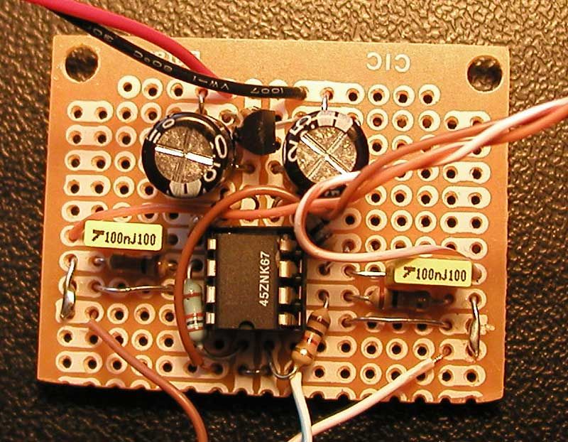
Progress: I have everything wired up right, I think. The power supply tests fine. My signal test failed, probably because the temporary test leads weren't soldered in. I just jammed them in. Soon I will solder in some hookup wires and do another signal test.

Concerns: My soldering iron sucks ass. I guess I shouldn't really expect more from a $5 Rat Shack iron. I'm currently thinking about dropping $40-50 on a basic Weller iron with variable temperature and changeable tips. No other current problems... but if my second signal test fails, I'll be up a creek.

Pictures
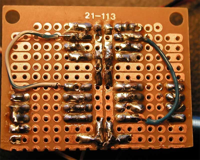
b2.jpg


b2r.jpg

This is why you shouldn't use a fat-tipped, 30-watt iron for something like this.
 

Users who are viewing this thread

Back
Top