


majkel
Headphoneus Supremus
- Joined
- Jun 1, 2007
- Posts
- 2,783
- Likes
- 64
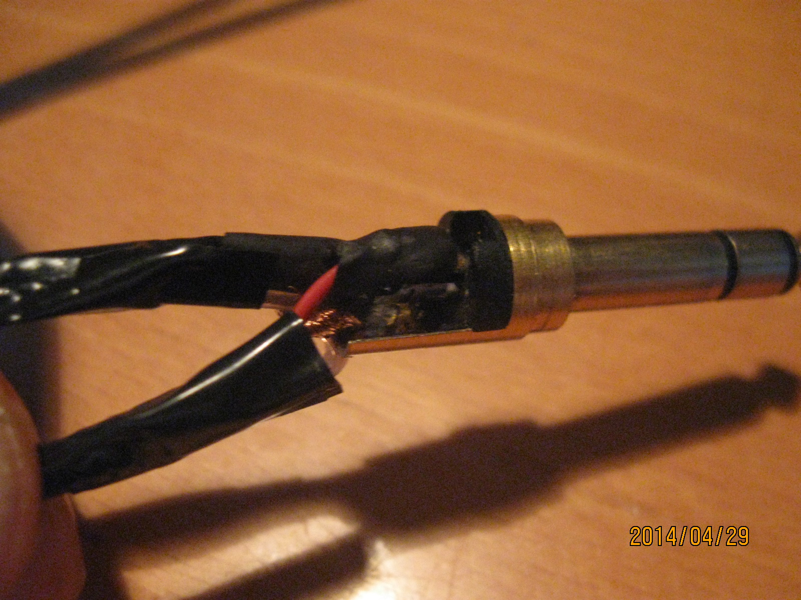
The modification is easy, invisible and flawlessly reversible. The first step is to disconnect the cable shields inside of the jack plug. This way you decrease the capacitance between the hot wires and the ground. Another step is to separate galvanically one shield from another so that they don't create short circuit. This step is even more significant as you decrease capacitive crosstalk between channels. Instead of shorted screens you have just a minute capacitance remaining between them. So, when you cut or de-solder them off the jack plug, you have to isolate the rest of the copper with insulation tape so it doesn't short with any other pin and the screens don't short together. The white wires remain connected, of course. You have to be careful while distinguishing the copper strands of the shield from the white wire strands. The results are:
- wider soundstage with great feeling of immersion in the music
- I finally enjoy Barocco music like Branderburgian Concertos
- I enjoy classical more
- better microdetail retrieval, slight roundedness in the sounds that some people reported, disappeared
- the Stax Demo CD sounded uncovincing before the mod, and it's one of the best real life illusion after the mod
I made a circuit so that I could short the screens together back and then re-connect them to the ground pin of the jack plug. In such a quick comparison you realize that with the stock connection there is something wrong. Actually, I repeated this experiment because I had done it two years ago prior to making my first DIY re-cable of the Creative Aurvana Live! Then I checked all the combinations of connecting the screens - grounded, floating, shorted, and then knew which was sonically and electrically the best. Even when some handbooks say how to connect the screen, it concerns static signal measurements in general. Here we have music and we care more about transients than steady states, so noise cancellation is less important than undistorted transients and impulses.
The mod is easily reversible by re-soldering the disconnected screen wires. When you like narrow and distant soundstage with small size imaging - don't do it. Otherwise, enjoy! Give yourself at least an hour to discover the new sound after the mod. For me there is no coming back.
Below are some instructions for those who don't know the Neutrik NP3X-B plug mechanics.
1. Grab the metal jack enclosure tight and twist off the plastic cable shield. The metal enclosure will fall off towards the jack tip.
2. Pull away the plastic shield towards the headphones.
3. Remove the blue strain relief by unbending it and pulling aside.
4. Look at the soldering of the ground pin. There are two white wires and two shields connected. Un-split the shield wires and disconnect them (cut off, de-solder)
5. Un-split and disconnect left cable screen from the right one.
6. Bend both shielding wires backwards and wrap around with a tape. To make it easier, cut the outer sheath along the middle on a 1/4" distance.
7. Place back the strain relief so that all three wings surround the cable and the bottom border fits the jack tip shaping.
8. Pull back the plastic shield.
9. Put the metal enclosure onto the jack, keep the plastic shield tight and twist on the metal enclosure until the whole thread is hidden. Done.
- wider soundstage with great feeling of immersion in the music
- I finally enjoy Barocco music like Branderburgian Concertos
- I enjoy classical more
- better microdetail retrieval, slight roundedness in the sounds that some people reported, disappeared
- the Stax Demo CD sounded uncovincing before the mod, and it's one of the best real life illusion after the mod
I made a circuit so that I could short the screens together back and then re-connect them to the ground pin of the jack plug. In such a quick comparison you realize that with the stock connection there is something wrong. Actually, I repeated this experiment because I had done it two years ago prior to making my first DIY re-cable of the Creative Aurvana Live! Then I checked all the combinations of connecting the screens - grounded, floating, shorted, and then knew which was sonically and electrically the best. Even when some handbooks say how to connect the screen, it concerns static signal measurements in general. Here we have music and we care more about transients than steady states, so noise cancellation is less important than undistorted transients and impulses.
The mod is easily reversible by re-soldering the disconnected screen wires. When you like narrow and distant soundstage with small size imaging - don't do it. Otherwise, enjoy!
Give yourself at least an hour to discover the new sound after the mod. For me there is no coming back.Below are some instructions for those who don't know the Neutrik NP3X-B plug mechanics.
1. Grab the metal jack enclosure tight and twist off the plastic cable shield. The metal enclosure will fall off towards the jack tip.
2. Pull away the plastic shield towards the headphones.
3. Remove the blue strain relief by unbending it and pulling aside.
4. Look at the soldering of the ground pin. There are two white wires and two shields connected. Un-split the shield wires and disconnect them (cut off, de-solder)
5. Un-split and disconnect left cable screen from the right one.
6. Bend both shielding wires backwards and wrap around with a tape. To make it easier, cut the outer sheath along the middle on a 1/4" distance.
7. Place back the strain relief so that all three wings surround the cable and the bottom border fits the jack tip shaping.
8. Pull back the plastic shield.
9. Put the metal enclosure onto the jack, keep the plastic shield tight and twist on the metal enclosure until the whole thread is hidden. Done.


