keberwein
New Head-Fier
- Joined
- Apr 10, 2017
- Posts
- 14
- Likes
- 20

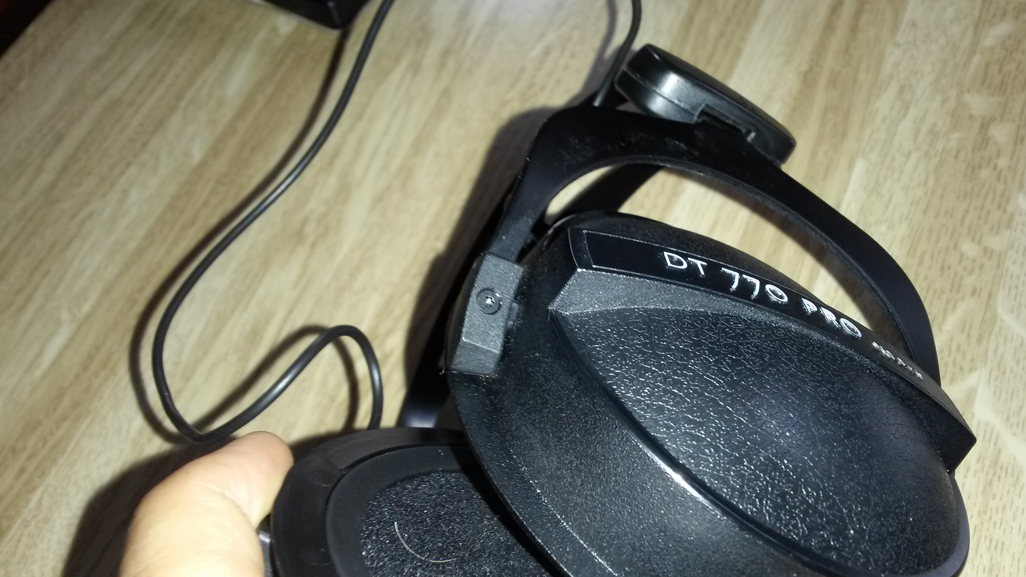
This is a headphone modification for the Beyerdynamic DT770 Pro. The 250 ohm model was used for this mod, but other models should respond well. The mod includes:
- Balanced re-cable and re-wire. Making the headphones fully balanced, duel entry mini XLR to 4 pin XLR.
- Internal sound dampening / audio witchcraft based on Bill P's mod.
- Custom paint job and balanced cable.
The dampening modifications tune the sound of the DT770 without changing it completely. Overall, I would say this mod changes the DT770's signature "V-shaped" to a more linear experience. The high-end is pushed back, allowing the mid-range come forward more than before, while the low-end remains largely unchanged. See the "Pad Rolling" section for more on this.
Tear Down
Materials
- Trox T6
- Trox T9
Here are the trox T6 on the ear cups.
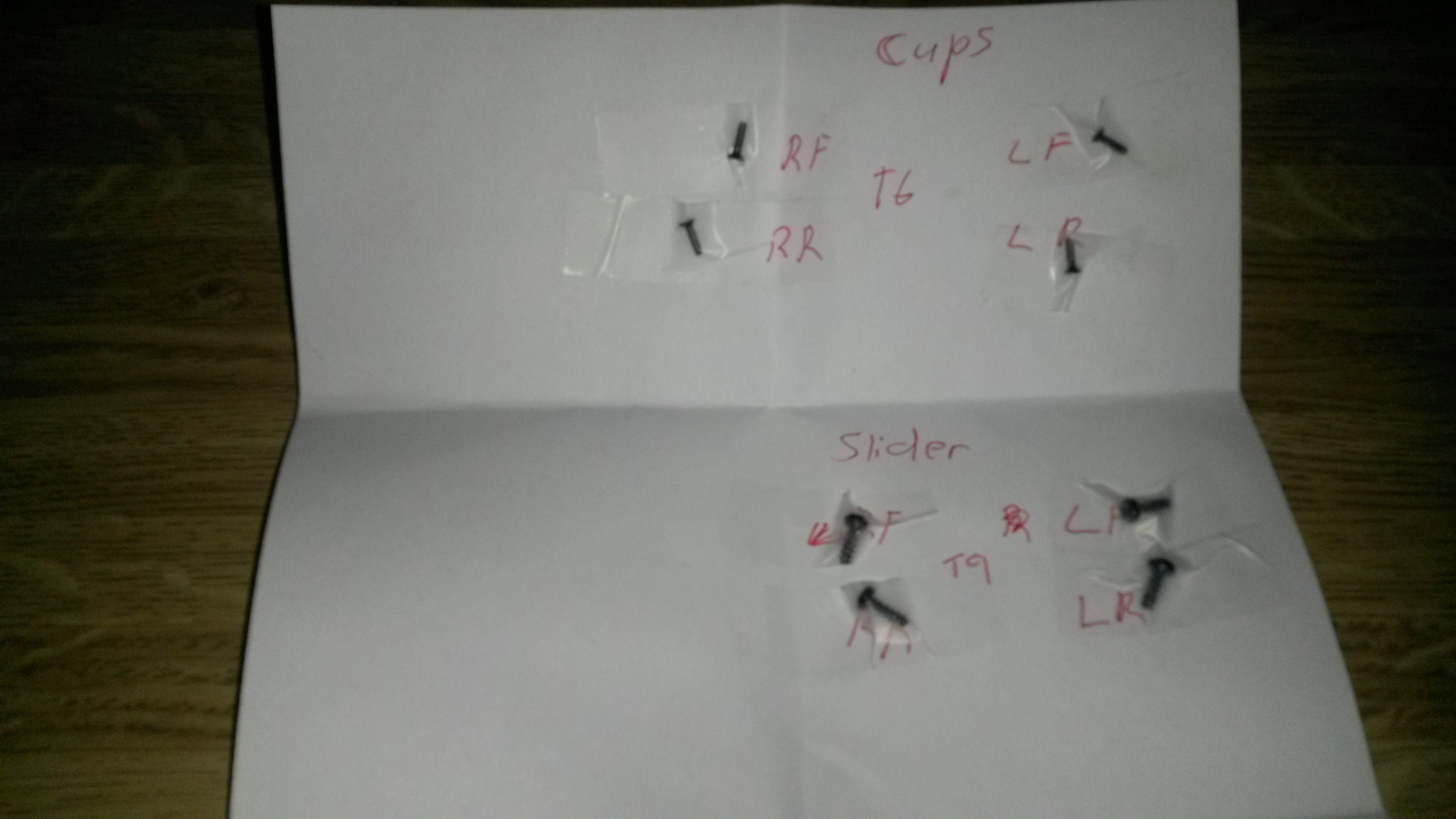
Pro-tip: Make a sheet with the screws taped in place along with the screw size and position. This comes in really handy if you don't plan to do all this in one day!
Removing Drivers
Each ear cup has a "retaining ring" that holds the driver in-place. This can be pried out with a mini-screwdriver with not too much drama, just be careful not to damage the driver. Sorry, I forgot to take a picture of this, but it will be obvious once the pads are off.
There is also a cotton ring and plastic ring on the back of the drivers. Both of these should slide off easily.
Balanced Recable
Materials
- Mini XLR, male 4-pin, Redco TB4M.
- Desoldering wick, solder, and soldering iron.
- Wire, a couple of inches of your favorite. I think I used some Canare L-4E5C that I had laying around from other cable projects.
- Drill or Dremel. I used a 3/8 drill bit, but if I had to do it again, I would use a Dremel to be a bit more precise.
WARNING USE LOW HEAT: The tree terminals are soldered directly onto the drivers. If you apply too much heat and break one loose--just throw the headphones away! If you've never used a desoldering wick, check YouTube.
There is a decent amount of solder on each terminal. Using about fifty-percent heat on my iron, I had to make two or three passes to get the solder off.
It's best to use a "hit-and-run" technique. If you feel the terminal start to move, even a little bit, pull the iron away and let it cool down before going in for another pass.
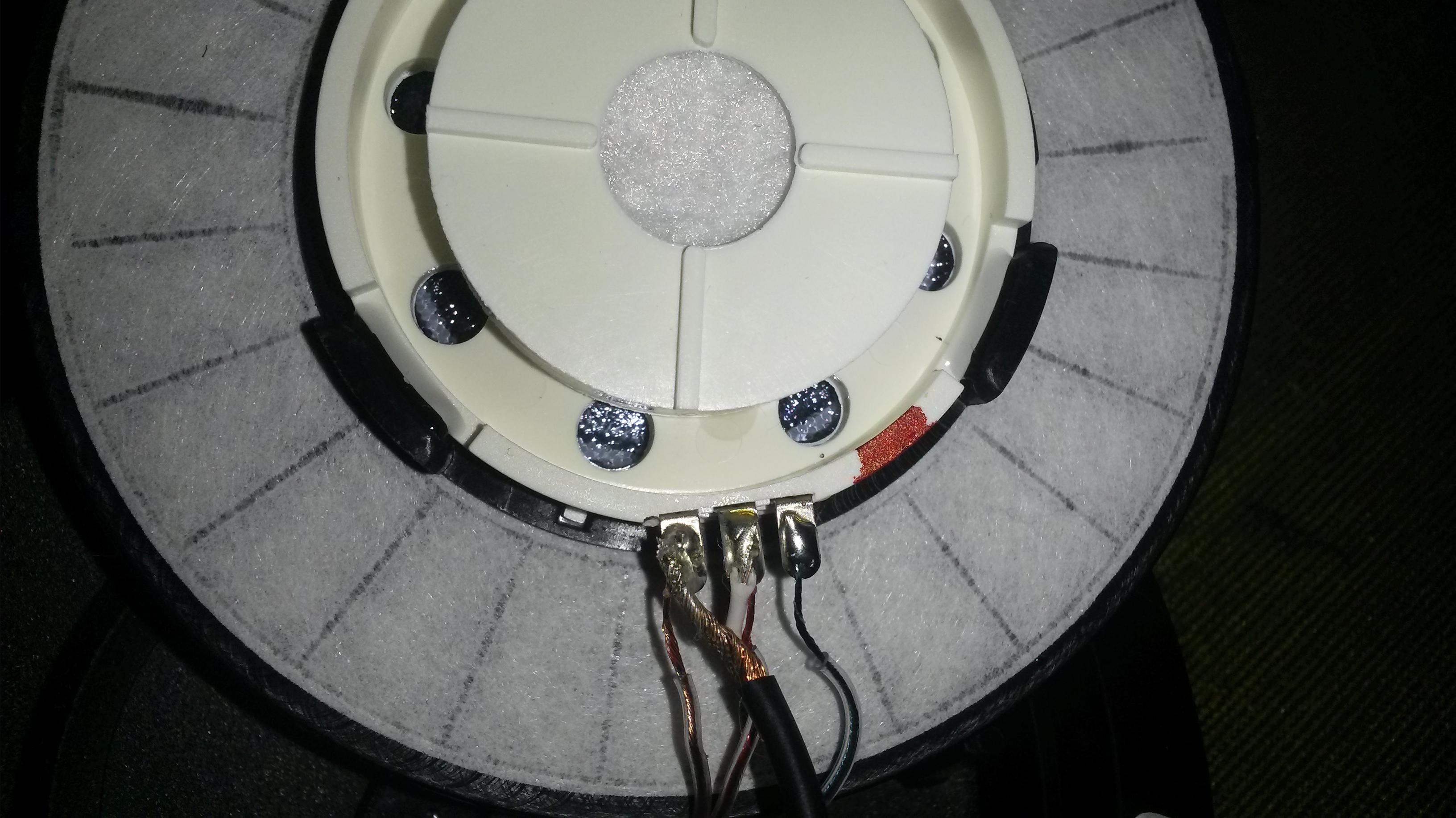
Below is the left driver before desoldering. Note the red paint mark on the right. This came from the factory, and signifies the positive terminal. I've seen older models use a gold mark instead of red. Make sure both of your cups have this, and if not, mark it. The positive terminals are on opposite sides on each driver. More on that later.
- Left terminal (as pictured): Ground for left and right drivers.
- Middle terminal: Hot from the other driver that came across the headband. Not directly connected to this driver.
- Right terminal: Hot for this driver.
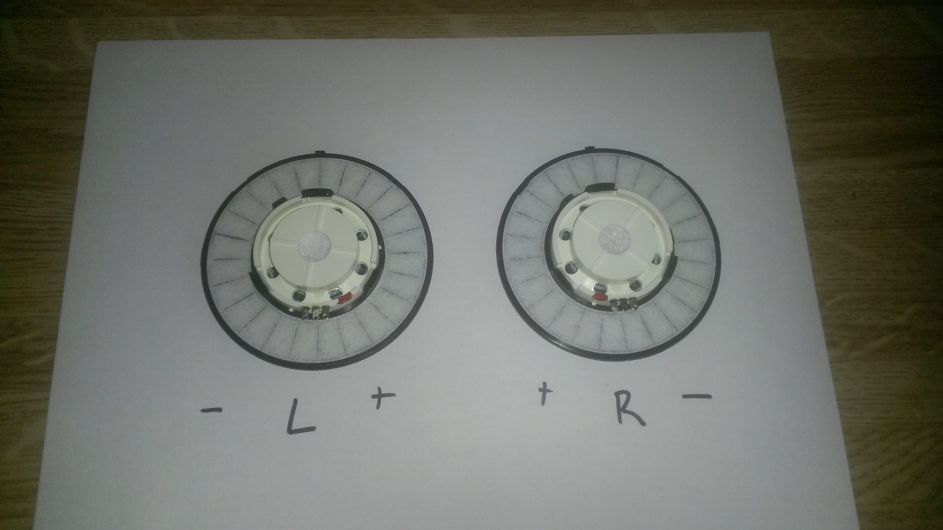
Below is both drivers desoldered with a diagram of the positive and negative terminals. Notice how they are on opposite sides. Since this is a balanced re-cable. We won't use the middle terminal at all.
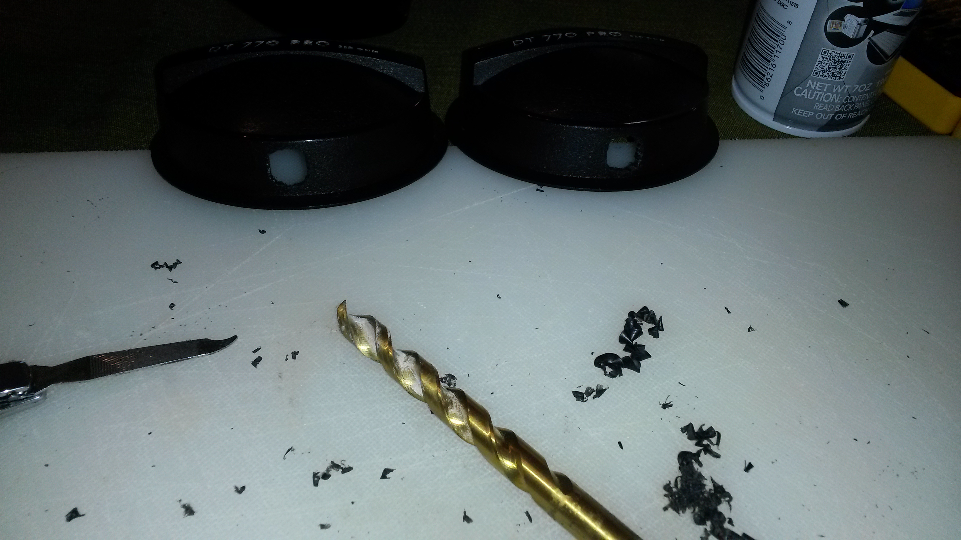
2. Ear Cup Modification
Assuming everything is desoldered without much drama, it's time to drill the ear cups.
WARNING TRICKIEST PART OF THIS MOD: Make the holes to the front side of each cup as much as possible. On the first version of this mod I centered them and the drivers would not fit back in the cup properly. Again, holes toward the front! To expand on this, here's a DYI blog that talks about the same issue, about half-way down the page.
Problems and Gotcha's
- The Redco XLR-males that I used came with a nice nut and washer, but once in-place, the nut was too wide and the driver would not sit correctly.
- Remember the "retaining ring" that we took off to get the driver out? Yeah, so that's going to need to go back on with the driver in-place. The problem here is, if the XLR-male isn't toward the font-side of the cup, the driver and retaining ring won't fit right.
- Don't use the nut that the XLR-males came with. Instead, I held the drivers in-place with some industrial strength epoxy. Make sure everything sits correctly before using any epoxy.
- On one of my ear cups, the left I think, the driver would not sit correctly even without the nut. I had to use a Dremel to shave about 1 mm. off one side of the connector itself so the driver would sit flat. I got lucky here, shaving too much off the connector would completely break it. Again, it is very important to have your holes at the absolute front of the ear cup.
3. Soldering the XLR
Each connector has four pins, but each cup only has one hot and one ground. Therefore, we have to "bridge" the pins on the XLR. Anyone who has made custom balanced cables before will be familiar with this.
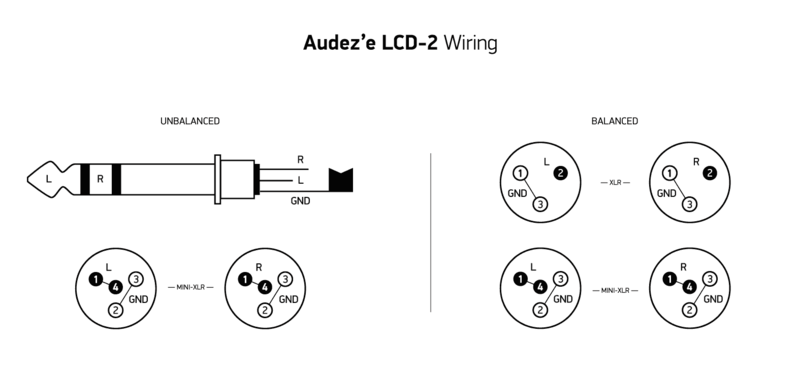
Below is the wiring diagram for the pins. Nearly all after-market 4-pin cables use the Audez wiring schematic. Pins one and four are the hot and pins two and three are the ground. To connect the pins, we will strip each wire to the appropriate length and make two solder points, one on each pin. Remember, we don't have to use a ton of solder, just a little bit will work, and a bit of extra flux never hurts.
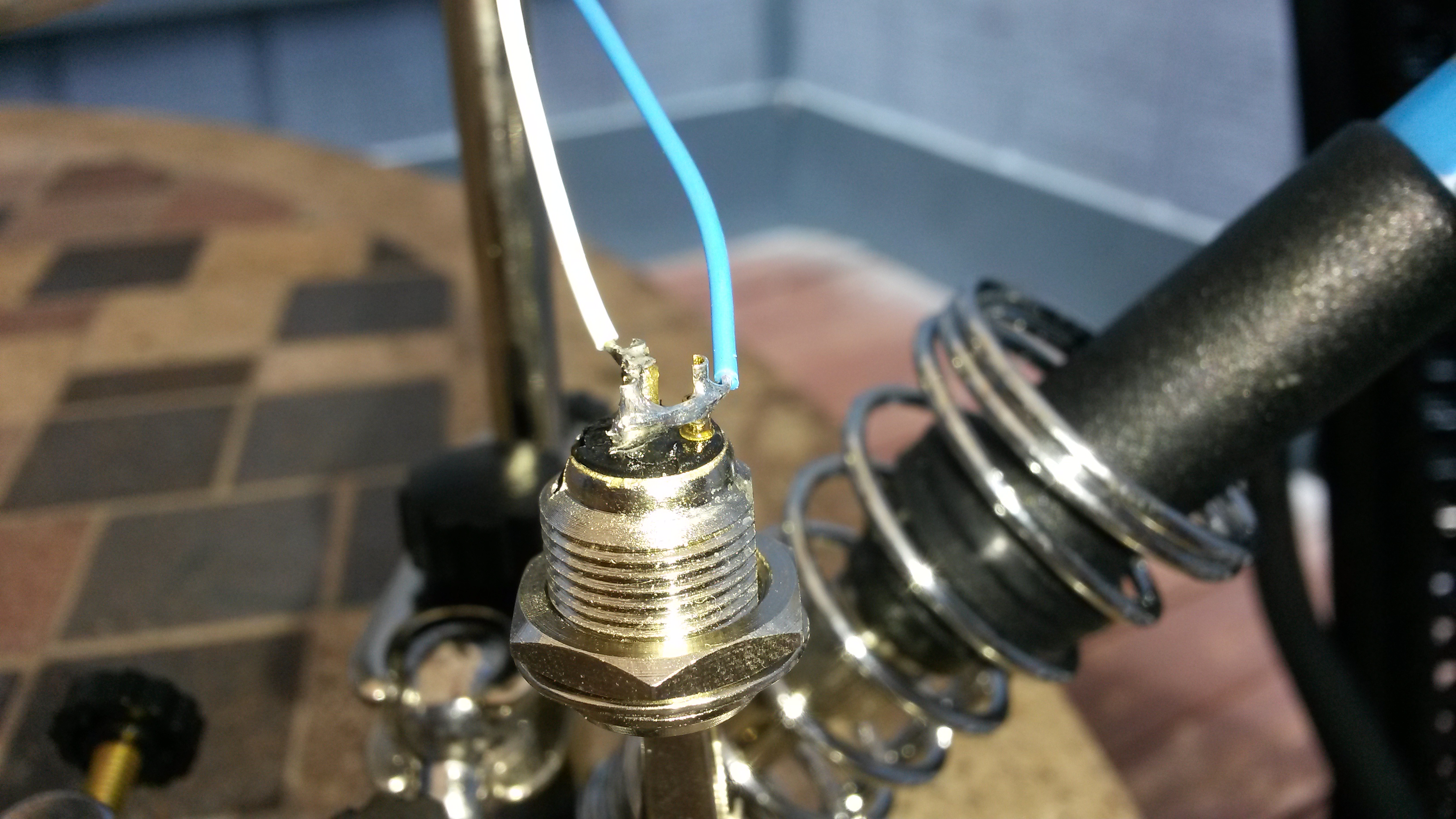
Below is an example of the "bridge technique." The wires will come out to the side, but that's good, because that is the way our ear cups are designed to accept them. *NOTE:* The "bridge" technique will not work for the headphone cable, since those have to come out straight. For that, we will use a "jumper technique." More on that in the cable section.
Pro-tip 1: Be consistent. I soldered white to hot and blue to ground. Colors don't matter, as long as they are the same on both.
Pro-tip 2: Have both wires exit in the same direction. This is how the wire restraints in the DT770 ear cups are set up.
4. Soldering the Driver Terminals
The next step can not be (easily) undone, so here's a quick check list:
- Holes are drilled?
- Made sure the driver and retaining ring will fit as they should with the XLR in-place?
- XLR wires have been soldered and "bridged?"
- Any painting has been done already?
Before we do anything, let's make sure we know which wires are hot and ground on each XLR. In the step above, we soldered `white` and hot and `blue` on ground. It doesn't really matter, just keep it consistent and know which wires go where.
Again, here is the wiring diagram for the drivers.
Although not necessary, if you have a "helping hands," now would be the time to use it. I slid a sheet of aluminum foil between the terminals and the back of the driver, just in the off-chance any solder dripped down. The nut is in the picture, but is not used--it can be tossed away, or saved for another project.
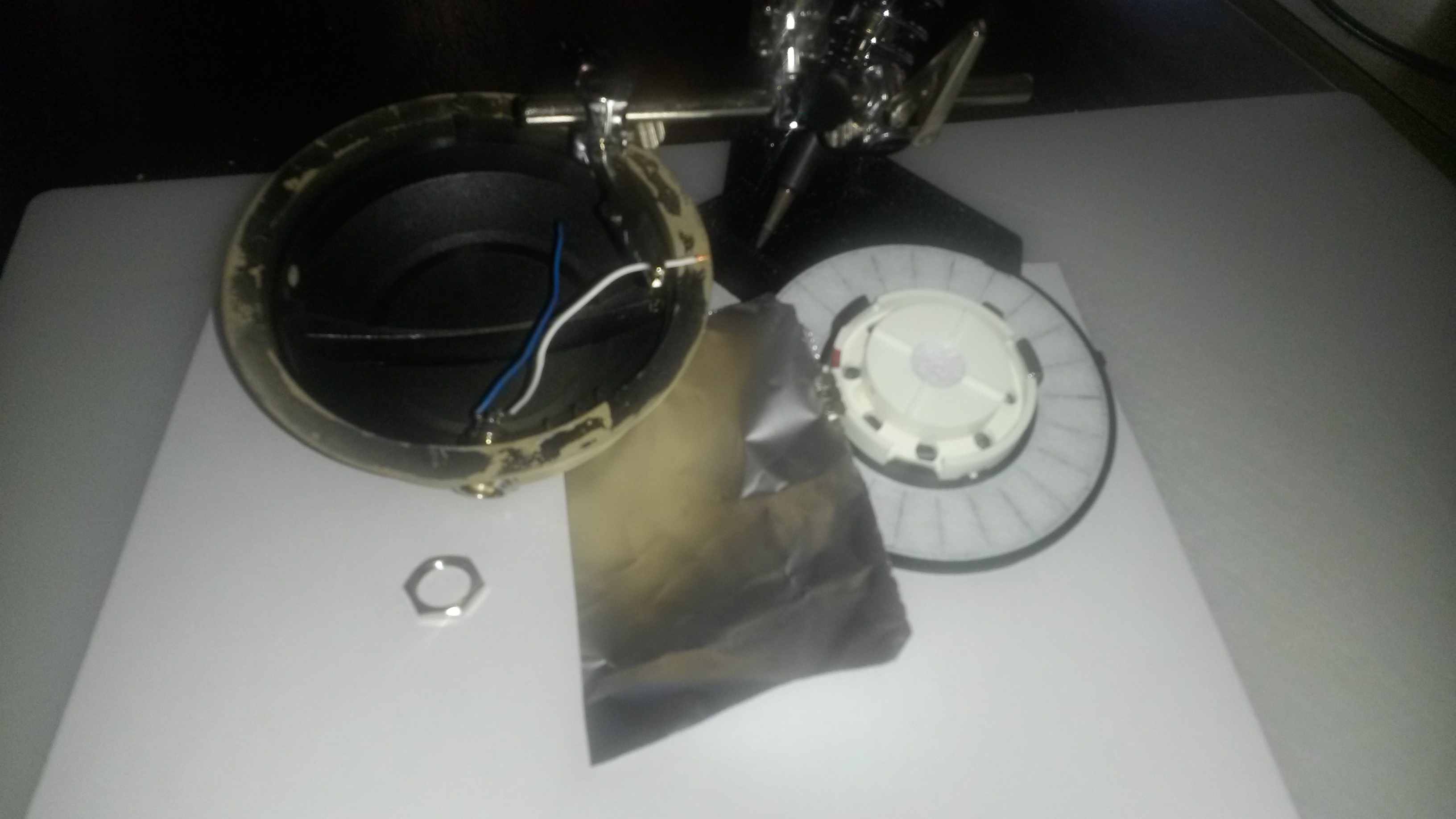
Once the soldering is done, fit everything back together and apply some epoxy to keep the connectors in-place. You may have to use some heat shrink or a small piece of rubber to ensure a good fit. Just make sure they are rock solid with no movement.
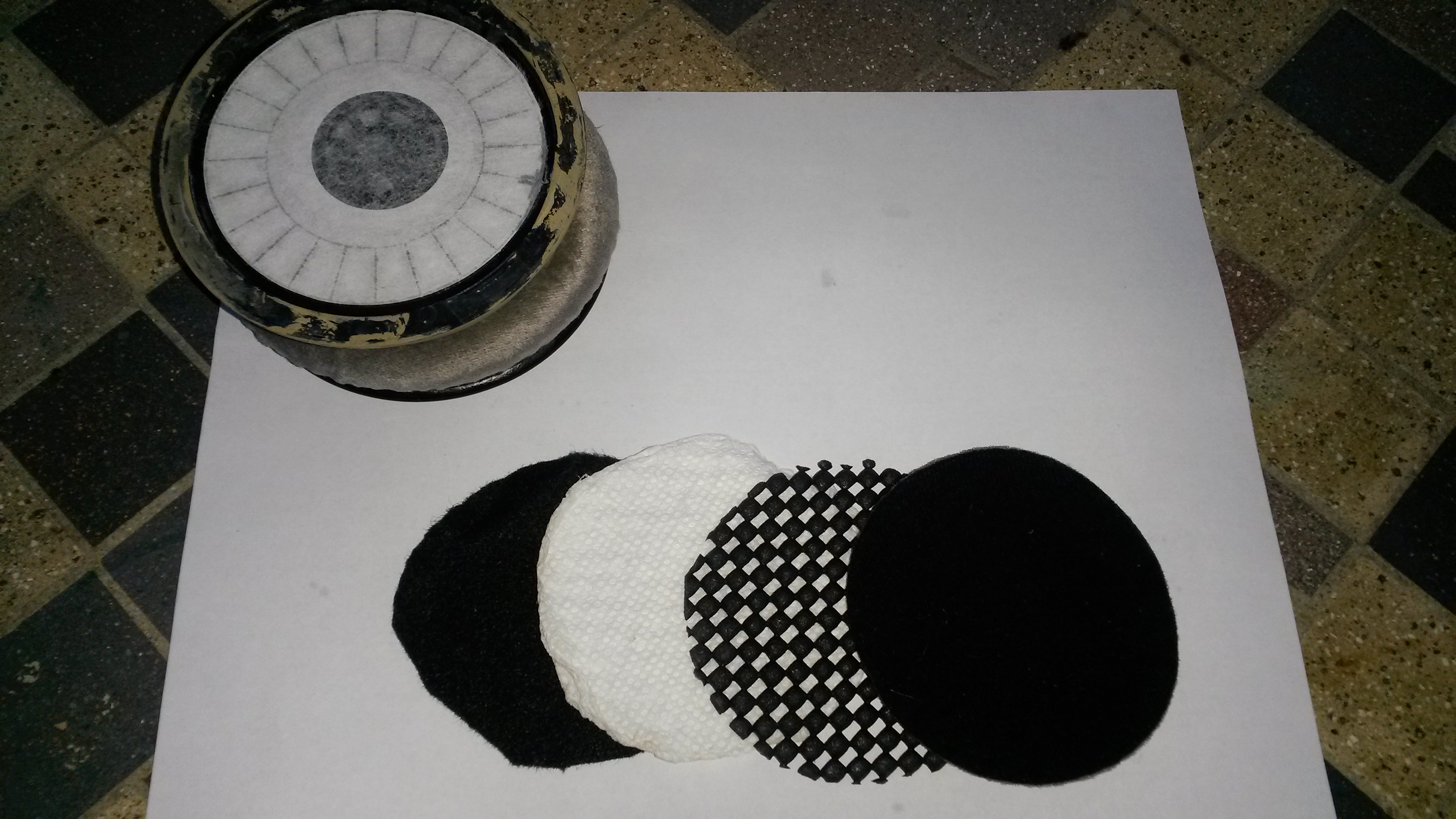
Sound Dampening
The dampening piece of the mod was borrowed from Bill P's mod. I experimented with various configurations of this mod, including ear pad rolling, but couldn't get a significant improvement over Bill's configuration. I eventually switched to ZMF round ear pads, but this was due to comfort and personal preference. The sound dampening works well with the stock DT770 pads.
Below is a picture of the order of the dampening material I used. The top piece of felt is the stock piece from the DT770's. The only difference I made to Bill's mod was to switch the order of felt and paper towels. I used the felt against the driver instead of the paper towels. I think it allows for more detail in the mid-range, but that's based on my ears, not measurements.
Pad Rolling
Version 1 Stock pads: Sounds like a DT770 with a tuned down high-end. The bass remains unchanged, while the mids are slightly more forward.
Version 2 Brainwavz HM5 pads: Sound stage opens up a lot! More punch in the mid-bass, but bass becomes less controlled. Mid-range seems like it has more detail; this could be a side-affect of the more open sound stage. The high-end gets pushed back even further; probably due to the drivers being pulled away from the ear.
Version 3 ZMF lambskin pads: This is the current working version. The ZMF pads open the sound stage and bring more detail to the mid-range. They have more "crush" than the HM5 pads, so the driver sits closer to the ear (like its supposed to), and the detail in the high-end is maintained. Also, much more comfortable than the HM5 pads.
Future thoughts: Brainwavz HM5 velours would be worth trying out.
Last edited:
