beta22 phase1
Jan 14, 2010 at 3:08 PM Thread Starter Post #1 of 57

jh4db536

500+ Head-Fier
Joined
Sep 22, 2007
Posts
553
Likes
72
new year resolution im gonna make good on this goal lol.
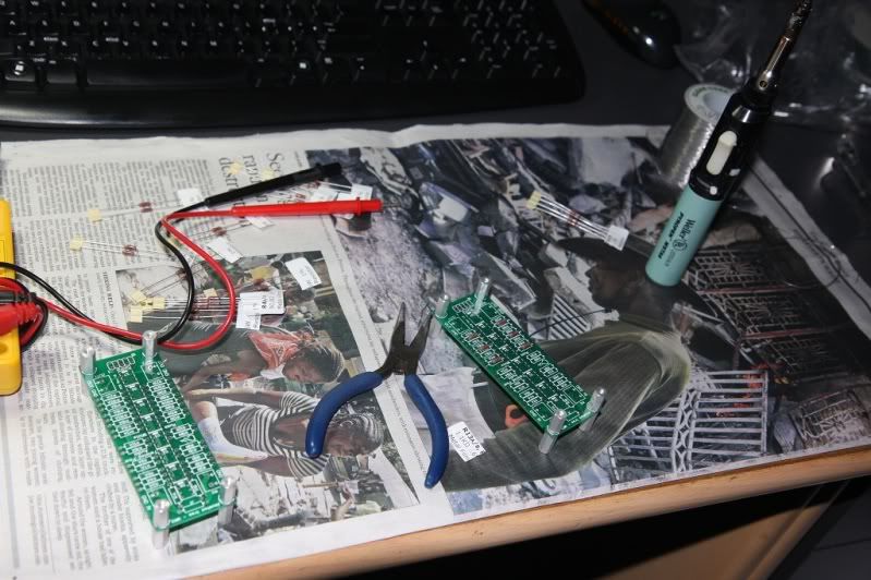
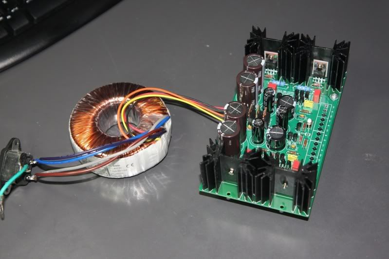
some parts came in yesterday.
this is gonna take me a couple months cause im really busy with work and i can only spend a few hours a week on this project.
i was actually surprised that the JA was a kit. i could use a warm up project anyway i havent soldered anything for a long time.

IMG_1342.jpg

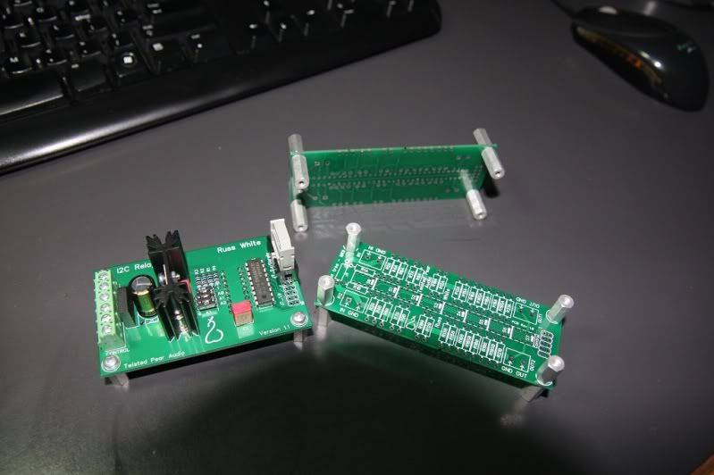
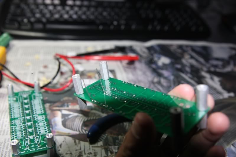
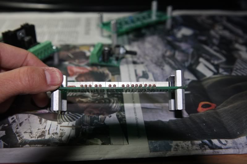
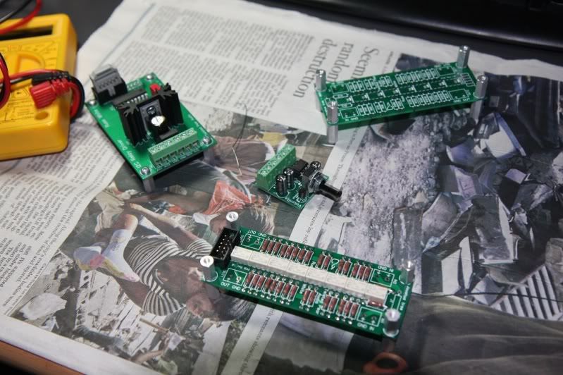
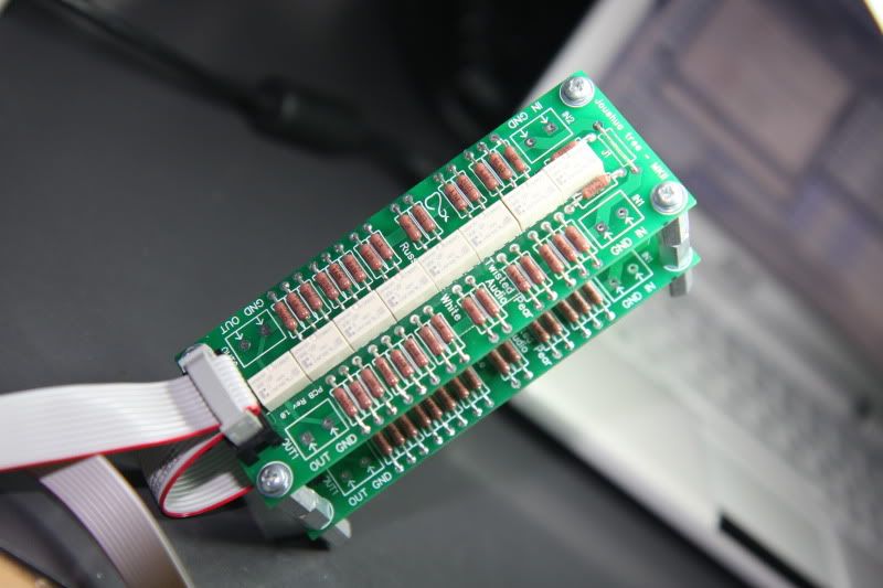
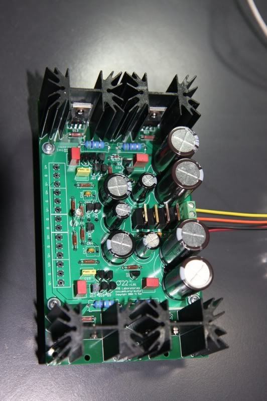
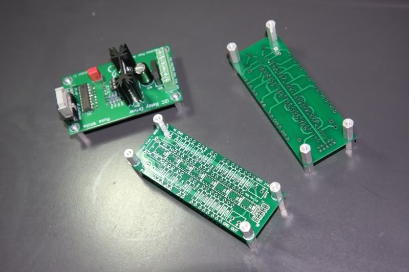
did the controller board yesterday

IMG_1344.jpg

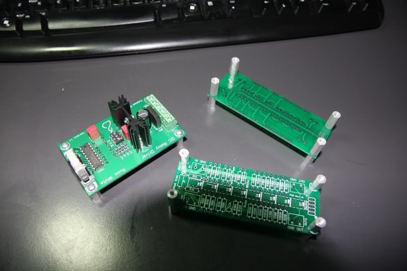
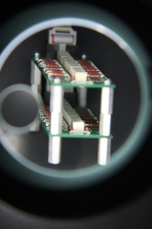
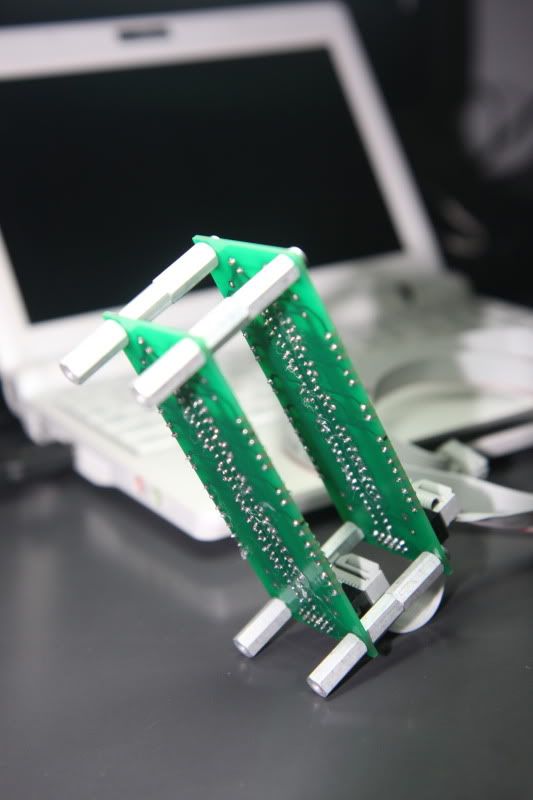
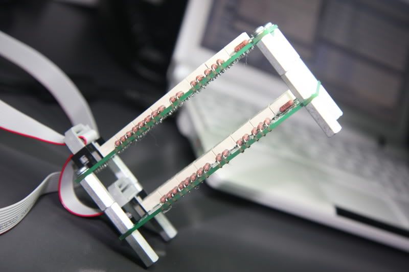
the relay boards and volumite tonight unless i have to pull an all niter at work
smily_headphones1.gif


IMG_1345.jpg
 
Jan 14, 2010 at 4:59 PM Post #3 of 57
Best of luck!
smile.gif

Take your time and do it properly, no half-great rush job.
 
Jan 14, 2010 at 7:11 PM Post #5 of 57
Good luck too !

I started mine as well... got almost everything I needed and started soldering. I'm quite anxious to plug it in.... I must admit it's my 1st DIY project but so far so good. (I know I shouldn't start with such a project)
I also need to stress this thing cost more than anticipated. Taking into account AC plug, hook up wire, connector and so on.... things add up pretty fast
smily_headphones1.gif
 
Jan 15, 2010 at 7:20 AM Post #7 of 57
nothing sophisticated...i have a AOYUE936 soldering station (i preferred to use the gas pen) and harbor freight meter. something about cordless and the tip on that thing gets me better results. i think the temp is perfect also.
IMG_1346.jpg


63/37 solder; checking for cold joints. btw i verified all the resistors before i populated the board.
IMG_1348.jpg


im still a little bit rusty
IMG_1352.jpg


1 more JT relay board to go...
IMG_1350.jpg
 
Jan 18, 2010 at 5:23 AM Post #9 of 57
Looks good so far
smily_headphones1.gif


Good luck with the build !

Peete.
 
Jan 24, 2010 at 1:42 AM Post #10 of 57
this was a little bit more difficult than i thought. for some reason i had a really hard time with the box caps, the damn solder wouldnt flow correctly i dont know why (no matter what i did it flowed upwards and was repeling the circuit board even though gravity was on my side). i had to use my AOYUE936 to get this one right. i thought i screwed up when i fired it up and got some bizzare voltage readings, but my DMM battery died. I think it's time to get a Fluke...anyway the output is fine
smily_headphones1.gif


the IEC recepticle was for testing purposes only. i gambled without a fuse hahah

IMG_1358.jpg


IMG_1361.jpg


IMG_1363.jpg


IMG_1366.jpg
 
Jan 24, 2010 at 1:50 AM Post #11 of 57
Just a quick note on the JTA... make sure the ribbon cable is fully engaged in the pins of the connector. I was having problems with one side and eventually figured out this stupid mistake.

I think I have the same Centech harbor freight DMM. It's not great, but I've built a few betas, a couple minimaxes, and a bunch of other stuff with it. Frankly, I was looking for a new DMM myself but then figured I had already gotten this far with a $5 one. Save my money and put it towards some new cans or something.
smily_headphones1.gif
Let me know if you do get one and if you think it was worth it though!
 
Jan 24, 2010 at 2:14 AM Post #12 of 57
yeah i'll probably just borrow the 'fluke' for now. i know many people who have one and use it as a battery tester lol.

thanks for the advice on the JTA ribbon cables, i checked continuity on every header from each board back to the control board, so i think it'll work fine.
 
Jan 25, 2010 at 2:46 PM Post #14 of 57
damn, i went on a 5 hour soldering marathon on sunday and i only finished half of the 1st Beta22 board (3 more to go plus chassis...). i wanted to finish the board, but i forced myself to stop before would i make mistakes. How are commercial sellers selling these things for under 2k without losing money?? This is a lot of work. ; cant wait until 4/15
frown.gif
 
Jan 25, 2010 at 3:21 PM Post #15 of 57
You did the right thing. I found that happening to me, it was four in the morning and I was almost there, every bit wants to keep on going but after 5-6 hours already you will probably make mistakes.

The transistors really pi$$ me off, I like to keep them all straight and neat but it is so hard to do, plus the holes for the CRDs/zeners are too big. I straightened all my box caps afterward by reheating and moving them.

The ones you hard trouble with were probably into the ground plane, max heat on the Hakko, flux, very low melting point solder, nothing would help; they will all be a pita.

By my fourth board I was completing them in 3-4 hours tho, you'll get faster!
biggrin.gif


I spent about 4 days, from 6-7pm till 3-5am :/ (wiring, testing, matching adds a lot too)
 

Users who are viewing this thread

Back
Top