Asus Xonar DX Mods!
Oct 4, 2008 at 6:59 PM Post #21 of 117
Quote:

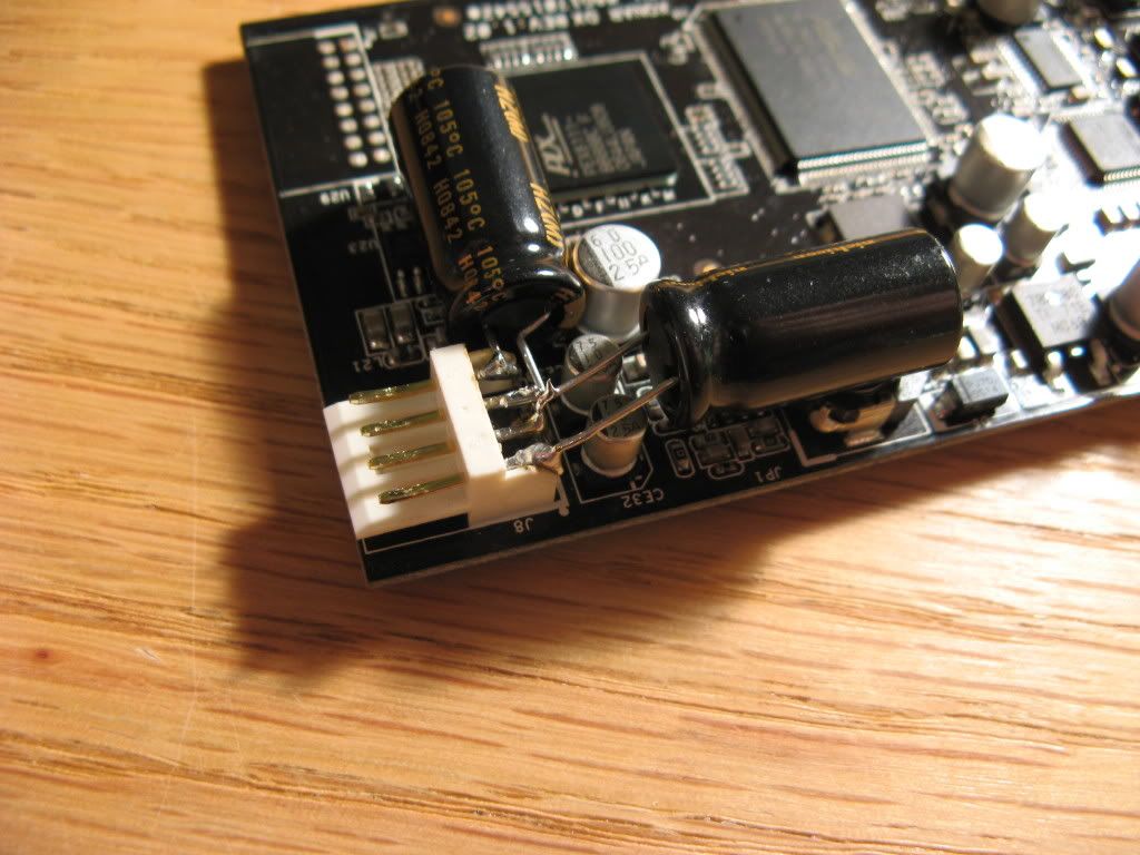
I would like to know what you done (in detail) to power supply caps near to external (floppy) power and on supply caps for opamp


It looks like more than it is. Those are just filter caps for the 12v and 5v supplies.
I used 4 electrolytics because I didn't have larger values at the time. I've now switched those for 2 larger ones. Those are bypassed with film caps.
Those film caps for the opamp are just ripple caps connected to ground.
 
Oct 5, 2008 at 6:45 AM Post #22 of 117
Ah I see, thanks for explanation. I might buy this card if I don't plan to do something with my money
smily_headphones1.gif


I have some stuff, like LT1364 and LME49720 opamp, Sanyo OSCON, Rubycon NX HQ and MBZ to try on this card, I might tap the 3.5mm to make RCA out from it too
 
Nov 16, 2008 at 7:21 AM Post #23 of 117
Looks interesting. Might need to try the mods on my DX once I have found a place to buy some audio grade caps in melbourne/australia.

I got NS to send me 3 LM4562 opamps so their fine.

What really pushed me to try and improve the SQ of the DX was when i compared it to my Arcam CD72 player, the DX just didn't have the depth and fidelity that the CDP had.

Anyone got pics of their modded DX's? First sound card mod so not too sure how to go about it, the opamp and output cap replacement looks simple enough. As well as the power filtering, although i could do with a diagram or picture
bigsmile_face.gif


Are the Sanyo OSCON caps recommended for the PF caps?

What sort of spec requirements are there for say the output couplings and power filters. Im finding it hard to buy Nichicon/Sanyo/BG and other high end audio labeled caps. There may be Rubycon caps in the local electronics shop, but how suited they are for this mod i do not know as i have little knowledge of what makes a good cap for the job at hand.
 
Dec 20, 2008 at 5:48 AM Post #24 of 117
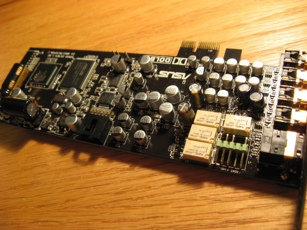
I finally cleaned up my early hack job of this card.
I have a soic opa2107 mounted. Nichicon KW decoupling caps, and Black Gate NX hi q coupling caps.
Also Nichicon ultra low esr HZ 1200uF caps decoupling the power supplies.

IMG_1920.jpg

IMG_1922.jpg


**now it fits a standard single slot
 
Feb 3, 2009 at 9:26 AM Post #25 of 117
Hi!
Since I'm a beginner at electronics, even if I know some things and can solder pretty decently, I got some questions.

What exactly is the purpose of the coupling and decoupling caps in this design and what kind of capacitor is prefered in this application? I can understand if you don't want to spend time explaing basic stuff, but I would like to get a grip about it all. This thing has been a questionmark for me some time now.

As for the powersupply caps at the floppy connector, would two 470uF Elna Cerafine caps work? I got some left over from an earlier project.

Sorry for my limited knowledge of theese applications, I'm trying to learn but there is a big lack of educational material for me to learn from.
 
Feb 4, 2009 at 12:12 AM Post #26 of 117
Quote:

What exactly is the purpose of the coupling and decoupling caps in this design and what kind of capacitor is prefered in this application?


Rather than try to reiterate information that can be found on the web I will tell you where to look.
First, if you want to have a deeper understanding of electronics it is best to start with understanding the 3 basic circuit components: resistors, capacitors, and inductors. You can find in depth articles on each of these on wikipedia. The question is how deep or superficial you want your understanding to be. These topics go very deep and you can take right down to the quantum level and presumably beyond.

As for coupling and decoupling the two principles are high pass and low pass filtering, respectively. You can find these topics on wikipedia too.
A high pass filter is where a 'coupling' capacitor is used. Here the idea is to filter out very low frequencies and most importantly to block 0Hz or dc voltage.
A decoupling is basically the inverse. Here we want to get rid of everything but dc voltage by shunting higher frequencies to ground.

Quote:

As for the powersupply caps at the floppy connector, would two 470uF Elna Cerafine caps work?


For the power supply caps these will be fine so long as the voltage tolerance is greater than or equal to 16V. These are decoupling caps, btw, because we would like to have only dc power with no superimposed ac ( ie a 'clean' power supply).
 
Feb 4, 2009 at 11:31 AM Post #27 of 117
Thank you, I've been reading a bit but since most articles aim at people with understanding I don't have I've been running into some trouble. Almost everything I know is self learned, and hence there are some gaps. But you answered my question perfectly. The answer you gave was just what I wanted to know, now I got an understanding of it and know how to go from here. Thank you! Now it makes a lot more sense to me, before I was a bit unsure.

I'm actually starting an electromechanical education later this year, I got an interest but I am by far not versed enough in their applications even if know what the basic components themselfs do.

I know how highpass and lowpass applications of capacitors work, and now I understand their use as well. A great many thanks!

EDIT: I got a bit confused in your main post regarding this:

Quote:

Mod 2: Quality High Pass Caps

EDIT this is a low pass filter. It is probably meant to remove high frequency noise. So this cap mod replaces the cap that is decoupling the i/v opamp (and forming the low-pass filter
This is not as significant as Mod 1.
I used the same method to replace the integrator caps


That's also why I got a bit unsure, first it says high pass, then lowpass and then talk about integrator caps. I got a bit confused, guess it shows that I'm not educated enough. I'm seeing this as a learning project in understanding plus getting something out of it.
 
Feb 4, 2009 at 9:10 PM Post #28 of 117
Quote:

That's also why I got a bit unsure, first it says high pass, then lowpass and then talk about integrator caps. I got a bit confused, guess it shows that I'm not educated enough. I'm seeing this as a learning project in understanding plus getting something out of it.


I think what it shows is that that post was very confusing. Blame it on my lab ethic. We're always taught never to erase but just add edits. In this case that isn't helpful at all. So I've gone and edited this to be more useful as a guide.
Let me know what you think.
 
Feb 5, 2009 at 3:30 PM Post #29 of 117
Quote:

Originally Posted by rds /img/forum/go_quote.gif
I think what it shows is that that post was very confusing. Blame it on my lab ethic. We're always taught never to erase but just add edits. In this case that isn't helpful at all. So I've gone and edited this to be more useful as a guide.
Let me know what you think.


Much better, now it's very coherent. Anyways, got any ideas on widely spread Higher Quality capacitors suited for the mod 1 & 2 on the card? I've been trying to get some Nichicon or Black Gates here in sweden but I can't even get my hands om some cerafines! :\
 
Feb 5, 2009 at 5:59 PM Post #30 of 117
Quote:

Much better, now it's very coherent. Anyways, got any ideas on widely spread Higher Quality capacitors suited for the mod 1 & 2 on the card?


I can send you some caps. Send me a pm.
 

Users who are viewing this thread

Back
Top