Asus Essence One Headphone Amp/DAC (CeBIT 2011)
Nov 11, 2015 at 9:38 AM Post #3,211 of 3,573
   
[...] We are in the middle of experiments (for unbalanced line only ofc.) removing ZU16, ZU19 OpAmps and put 0.01uf film capacitor betwin 4-8 legs and same for ZU23, ZU24 (XLR outputs). Easy shunt whitout solder. Capacitance value are part of experiments too. Sound clarity improvements are very interesting. You can experiment further puting electrolytic capacitors betwin 3-4 and 5-8 legs for I/V. (Do not use same method for XLR output).

 
Thanks RainfallSky!
 
I understand a capacitance between 4-8 legs, but why between 3-4 and 5-8, please?
 
Nov 11, 2015 at 10:01 AM Post #3,212 of 3,573
[quote name="raoultrifan"
From http://audiohobby.ru/dorabotka-asus-xonar-one.html (thanks again to Google translate) looks like the dual PCM1795 DAC is using all the 4 DAC outputs only when balanced external amplifier is used (another good reason to use an external balanced amplifier and balanced headphones). When using internal amplifier (LM49720+LME49600) or unblanced RCA outputs E1 takes the output signals only from I/V OPAMPs no. I and no. III; the OPAMPs II and IV remain unused (I believe only half of LPF OPAMPs are actually used). I wonder if other manufacturers are doing the same. For example, M2Tech Vaughan is using 8xPCM1795, so...perhaps Vaughan is using 8xPCM1795 in dual-mono config and 4-chips are used for unbalanced and all the 8-chips are used for balanced...I don't know.
[/quote]

Hi raoultrifan, thank you very much for your post, very informative and detailed :thumbsup:
So you think the Xonar in using just half the opamp for the headphone out and use all of them only for balanced output? If that's real that sucks because as other user here I spent a lot of bucks buying Muse/Burson opamp for tweaking the sound....
Just for record now I'm quite happy with 5 MUSE01 on I/V & LPS and dual lme49710ha for the Buffer (and I've got a couple of Burson Discrete Opamp V5 coming tomorrow), but all your finding are scaring the hell out of me!!
Also all this problem you are finding with the PCB & PSU relly worry me.
Keep up with your wonderull technical analysis!!
 
Nov 11, 2015 at 12:23 PM Post #3,213 of 3,573
 
Thanks RainfallSky!
 
I understand a capacitance between 4-8 legs, but why between 3-4 and 5-8, please?

 
Since electrolytic capacitors have polarity, capacitors should be inserted 3+, 4- and 8+,5-. So about why. It was idea of HIMIKATOR, he said he borrowed some ideas from Analog Devices OpAmp datasheets where on each power leg should be electrolytic capacitor connected to the ground. And since 3 and 5 legs connected to the ground, capacitors shunt each power shoulder.
 
P.S.: Last post i mistyped "partly" with "party". ))
 
Nov 11, 2015 at 3:15 PM Post #3,214 of 3,573
   
[...] each power leg should be electrolytic capacitor connected to the ground. And since 3 and 5 legs connected to the ground, capacitors shunt each power shoulder.

Makes sense, despite the fact that these OPAMPs already have decoupling caps around them, additional decoupling might help alot sometimes. So, have you found the best caps to provide the best sound, please?
 
[...] So you think the Xonar in using just half the opamp for the headphone out and use all of them only for balanced output? If that's real that sucks because as other user here I spent a lot of bucks buying Muse/Burson opamp for tweaking the sound....
Just for record now I'm quite happy with 5 MUSE01 on I/V & LPS and dual lme49710ha for the Buffer (and I've got a couple of Burson Discrete Opamp V5 coming tomorrow) [...]

Yes, 2 OPAMPs are used for RCA outputs (corresponding to 1/2 half of first PCM1795 + 1/2 of the second PCM1795) and the other 2 OPAMPs for the remaining 2 channels responsable for XLR outputs. And yes, you can actually spend half of money to try out I/V OPAMPs in Essence One DAC, but only for unbalanced tests.
Please tell us differences between MUSES01 and BURSONs. Thank you!
 
Nov 11, 2015 at 6:05 PM Post #3,215 of 3,573
Yes, 2 OPAMPs are used for RCA outputs (corresponding to 1/2 half of first PCM1795 + 1/2 of the second PCM1795) and the other 2 OPAMPs for the remaining 2 channels responsable for XLR outputs. And yes, you can actually spend half of money to try out I/V OPAMPs in Essence One DAC, but only for unbalanced tests.
Please tell us differences between MUSES01 and BURSONs. Thank you!

 
As of now on my Xonar I have 6 muses01 (LPF, I/V), 3 lme49710x2 (Headphone Buffer, RCA), 2 lme49720 on XLR.
Is practically a stock Essence Muses, as lme49710 and lme49720 are a "better" lm4562. It does sound quite analitycal, maybe a little on the bright side (opposed to my other 2 DAC, based on ES9023) perfect for taming my HD650.
By the end of the week I'll receive the burson V5 for the headphone buffer, I hope to hear a more engaging sound....
I'll report back to you next week!
 
Just to be clear, you mentioned only RCA and XLR in your previous post, would you please specify if on the headphone buffer it make use of all the opamp of I/V, LPF and Headphone Buffer? (or is it the same as RCA because is not balanced exit?)
 
Thank you in advance!
 
Nov 11, 2015 at 11:31 PM Post #3,216 of 3,573
   
Just to be clear, you mentioned only RCA and XLR in your previous post, would you please specify if on the headphone buffer it make use of all the opamp of I/V, LPF and Headphone Buffer? (or is it the same as RCA because is not balanced exit?)
 
Thank you in advance!

Headamp is getting the sound from the same OPAMPs like RCA outputs: 1'st and 3'rd I/V OPAMPs (ZU12 and ZU17). Feel free to eject the 2'nd and 4'th OPAMPS (ZU16 and ZU19) and you'll still hear the same sound on RCA and headphone outputs.
 
RainfallSky mentioned that OPAMPs are actually numbered, from left to right, as: ZU12, ZU16, ZU17, ZU19; that can be seen on this picture as well: http://tweak.just-click.ru/wp-content/uploads/2013/08/asus-xonar-one-output-stage.jpg, if you zoom in closely.
 
Nov 11, 2015 at 11:53 PM Post #3,217 of 3,573
   
Hi Raoul,
 
Does he give out the schematic for the DIY PSU?

Actually, looking closely to http://audiohobby.ru/dorabotka-asus-xonar-one.html I realized that there's a schematic over there. Please, check the below picture.

So, LM317/337 for the +/12V rails and 7805 for the +5V. By looking more closely to the picture, I still believe that he did a CRC filter before the power regulators, so the ripple should be almost non-existent on outputs. Actually, looks like he built a +/-15V PSU instead of +/-12V (be aware that not all OPAMPs can support +/-15V!); probably he wants to modify headmp's internal gain resistors to increase headamp's output voltage from 6.6-7V to 8-9V...I don't know, but increasing +/-12V rails to +/-15V, in conjunction with a low-gain/high-gain relay and a "relay command button" mounted on the back of Essence One is something I think about myself since couple of months. :) Please check Essence One headamp's schematic below:


Anyway, I still recommend LT1963/3015 for +/-12V and TPS7A47 for the +5V (or something better like Per Anders low-noise regulators).


Regards!
 
Nov 12, 2015 at 2:19 AM Post #3,218 of 3,573
  Makes sense, despite the fact that these OPAMPs already have decoupling caps around them, additional decoupling might help alot sometimes. So, have you found the best caps to provide the best sound, please?

 
I still use only 0.1uf film cap betwin 4-8 legs in I/V and XLR, but guys say about 470uf 16v and beter electrolytic caps at I/V sockets makes nice improvement. Let's add that each capacitor brand have unique sound character.
 
Nov 12, 2015 at 2:33 AM Post #3,219 of 3,573
Why not tantalums, like manufacturers suggested, by the way? TI and AD say that 2-3uF of tantalums + good film caps should be perfect. Only powerful buffers (like BUF634 or LME49600/49610) need 5-10uF tantalums (or >100uF electrolytics, but usually tantalums are the best).
 
I'll probably give it a try myself sometime, but like I said before, all E1 OPAMPs are already bypassed by electrolytics, especially I/V OPAMPs; just between +/-12V there are no caps at all.
 
Nov 12, 2015 at 5:10 AM Post #3,220 of 3,573
I don't have an answer for that question since it was HIMIKATOR idea not mine. That's a wide field for experiments. Good thing it's easy to insert capacitors in socket to find out what changed in the sound. You can also solder capacitors on another DIP-8 socket and insert it like regular DIP-8 OpAmp.
 
Nov 13, 2015 at 5:14 PM Post #3,223 of 3,573
Despite the fact that I had improved the +5V noise+ripple from my E1's PSU, here's how the +5V measured directly on the small SMD capacitor from PCM1795 looks like:


Not very good, I'd say, actually the +5V signal measured directly on PSU's plug looks better. 1.4mV p-p and a strange looking and non-linear signal that looks like ripple and that modifies it's shape, depending on the action E1 is doing (play PCM, play DSD, pause etc.). I paralleled few tantalums and also some KA capacitors on both caps directly connected to PCM1795, but useless: the signal looks still the same. :frowning2:
 
BTW, does anyone knows what an ARMv6-M processor does in this DAC, please? I'm speaking about Nuvoton M054ZAN from the back of the main PCB.


Core ProcessorARM® Cortex®-M0
Core Size32-Bit
Speed50MHz
ConnectivityI²C, IrDA, SPI, UART/USART
PeripheralsBrown-out Detect/Reset, LVD, POR, PWM, WDT
Number of I/O24
Program Memory Size16KB (16K x 8)
Program Memory TypeFLASH
EEPROM Size-
RAM Size4K x 8
Voltage - Supply (Vcc/Vdd)2.5 V ~ 5.5 V
Data ConvertersA/D 5x12b
 
Perhaps this is taking care of the software from within the PCM/DSD EEPROM from the motherboard?
 
Nov 14, 2015 at 8:50 AM Post #3,224 of 3,573
if someone is interested i selling my unit.
http://www.head-fi.org/t/786360/asus-xonar-one-headphone-amp-dac
 
Nov 14, 2015 at 4:48 PM Post #3,225 of 3,573
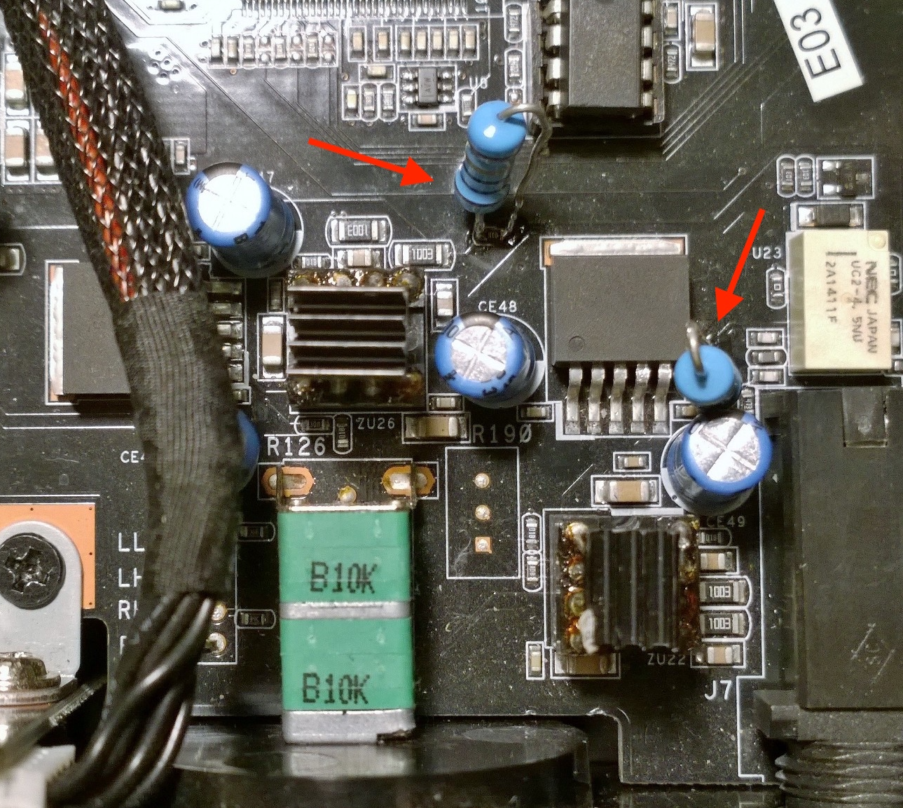
On a 2'nd thought looks like I paralleled the additional caps on 47uF caps (CE5, CE6, CE16, CE18) instead of 100uF caps (CE3, CE4, CE14, CE19). The 2x47uF caps for each DAC are for VcomL and VcomR reference voltage from inside PCM1795 DAC and there's no need to adjust these 2 caps.
 
So, I'm redoing this job now by paralleling existing 4 x 100uF/35V caps (2 per PCM1795) with additional 4 x 100uF/35V Nichicon KA and 4 x 10uF/25V tantalums.


As you can see, the +5V ripple+noise measured directly on the very small SMD capacitor (2mm nearby pin 23 of PCM1795) decreased from 1.4mV p-p (see my last post) down to about 1mV p-p (most of the noise is actually below 0.9mV).
 
I don't think there's something else I can do to this +5V signal to make it look better on my scope, unless installing 470uF caps (like M2Tech Young or Vaughan) in parallel with existing 100uF caps (CE3, CE4, CE14, CE19) and check if noise improves. Most likely ripple+noise will decrease a bit, perhaps somewhere around 0.8-0.9mV, but unfortunately I don't have right now at home decent low ESR 470uF caps, but I'll probably give it a try sometime.
 
BTW, I just measured ripple+noise of my ODAC, directly on ESS9023 +3.5V pin and it's around 4mV p-p, no matter what USB port I'm using on my Thinkpad laptop. So, I believe getting about 1mV for my Essence One PCM1795 chip might be OK after all...I don't know. :)
 

Users who are viewing this thread

Back
Top