Are these ebay BG capacitor legit? Also requesting IMod Capacitor suggestions. Why are some caps better than others?

Feb 20, 2011 at 5:56 PM Thread Starter Post #1 of 42

High_Q

1000+ Head-Fier
Joined
Mar 20, 2010
Posts
1,258
Likes
27
 
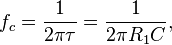
Equation for high-pass filter:


C=1/(2*pi*R*f)


Assuming I will use worst case scenario of internal impedance being R=10k ohm and human hearing limitation bounded at f=20Hz


I get C=0.7957uF


Are these black gate caps legit?  If so, are they even worth what they are selling for?

http://shop.ebay.com/i.html?_nkw=black+gate+nx+capacitor&_sacat=0&_odkw=black+gate+capacitor&_osacat=0&_trksid=p3286.c0.m270.l1313
 
 
I recently made an LOD with nichicon 10uF polar caps because they were smaller than the non-polar ones at the RadioShack.  Should I be content with them?  They do block out the DC as required, what more is there?
 
Now I am curious if caps do indeed have an effect on sound(hopefully positive), if I can get better sound from more quality caps.  If that is the case, any capacitor suggestions are welcome.  
 
Question:  Why are some caps better than other such as Black Gates?  Is it the material its made from?  Is it subjective?
 
Feb 21, 2011 at 10:19 AM Post #2 of 42
What a way to end a post... Is it subjective?
 
Caps and cap choice are very subjective. Check out this thread: http://www.head-fi.org/forum/thread/284863/orgy-of-capacitors-the-cap-thread  These are film caps that would never fit in a standard LOD; I think someone started a similar thread on electrolytic caps, but I could be mistaken.
 
A cap in the signal path will never be additive and is never better than a piece of wire, regardless of price, in terms of sound quality. The better caps do less damage sound-wise than inferior ones. Some of the boutique electrolytic caps use differing materials or additives to the electrolyte: Elna Cerafines used ceramic IIRC, Black Gate used graphite (also IIRC). If you want a good bang for the buck cap, check out the Elna Silmic IIs for an electrolytic cap. Since you only need 1uf according to your calculation, you could get away with a film cap although there would still be some rolloff an octave above the cutoff frequency. That is actually a low pass filter BTW.
 
As for the BGs in the link being legit or not... hard to say, but judging from where they are coming from, I wouldn't bet on it, particularly at the stupid insane prices they are asking. You can check out Michael Percy Audio's catalog for the selling prices (when he had them) for BGs. For example, the NX 100uf/50V are $13 in Percy's catalog (he is out of them now); the ebay link was asking $105 or something like that for one of them. Free shipping though :)
 
Feb 21, 2011 at 7:54 PM Post #3 of 42
Thanks for you detailed response.
Quote:
. That is actually a low pass filter BTW.
 

One thing though.  I have a problem with the statement above.  If that were the case we won't hear anything, and headphones will get screwed from the DC offset.  High pass means, its letting high frequencies through. I know that much as an Electrical Engineer.  Here's more detailed explaination, joneeboi explain it well..
 
Originally Posted by joneeboi 


The capacitance you need for the diyMod refers to the high pass filter that forms when you connect your diyMod to your amplifier. When you connect a series capacitor to a parallel resistor to ground (in the amplifier, this resistor is the volume potentiometer), it forms a first order high pass filter, which allows passes mostly high frequencies while attenuating low frequencies from the signal. DC power is, all in all, 0 Hz, a low frequency. Capacitance is the amount of charge that the capacitor can hold, and in our use, you only need a small amount of capacitance in the diyMod. The equation governing the size of capacitor in a high pass filter characteristic is


C = 1/(2*pi*f*R)


where C is the capacitance in uF

f is the frequency in Hz

and R is the input impedance of the amplifier.


Basically, we want to filer out the DC while passing as much of the audio signal as necessary. Since humans can typically only hear between 20Hz and 20kHz, the highest  lowest frequency you want to pass through is 20Hz, which we'll plug into the equation.


My explaination:


79e190943633c91aa660a4a9351087ab.png


where f is cutoff frequency(meaning that the lower bound cutoff frequency point, since you are letting in high frequencies), and you are passing everything over 20Hz(cutoff frequency).  By doing that you are filtering out DC(which has no frequency, f=0, since its not changing being constant), which is less than 20Hz, everything under 20Hz will not pass.


I guess EE school wasn't total waste of time.  :)

 
Feb 22, 2011 at 2:02 AM Post #5 of 42
your math is right, the corner frequency will be below 20hz with less than 1uf, but your conclusion is wrong. you are forgetting about the IMD (phase distortion) which occurs roughly 10x higher up. for a 10k input impedance i would go no lower than 8-9uf
 
1uf


9uf


another vote for silmic II here, i actually prefer them to bg. of course film caps would be better and you can find small film caps, but not large enough in value, fine for bypass though, so my current favprite is silmic ii bypassed with .22uf film
 
Feb 22, 2011 at 7:26 AM Post #6 of 42
Thanks for the response qusp.  Do you guys know of a part # on mouser or digikey if they carry the Silmic 2 caps?  If not, is there  a good site that carries the?  Just out of curiosity, can you explain the how you arrived at the distortion value? 
 
Feb 22, 2011 at 9:27 PM Post #7 of 42
Digikey has them, search for "elna rfs caps". Go from there.
 
Parts Connexion also stocks them as does Handmade Electronics, HiFiCollective and others. Just google 'elna rfs silmic'.
 
Feb 22, 2011 at 11:34 PM Post #8 of 42


Quote:
Thanks for the response qusp.  Do you guys know of a part # on mouser or digikey if they carry the Silmic 2 caps?  If not, is there  a good site that carries the?  Just out of curiosity, can you explain the how you arrived at the distortion value? 


its a pretty well known effect of capacitors that has to do with the input signal and output signal not happening at the same time,  check out tangent's website, or just google 'input or output cap' and 'phase distortion'. the math is in my post already, but if you need more google is your friend. capacitors are far from linear
 
Feb 23, 2011 at 12:10 AM Post #9 of 42
Qusp, what you state doesn't make sense.  You state IMD, intermodulation distortion and equate it to phase distortion.  Do you have understanding of those terms?  Do you know what intermodulation and phase means?  I have a feeling its something you got from google or heard from somewhere like all your collection of forum knowledge.  Trouble with that is you get knowledge without the fundamental background.  Like I said, its pretty common sense, lowest frequency we hear is 20Hz.  Think about that... and the meaning of modulation.  I don't even know if you are qualified to toss terms around.  Quite a collection of fancy cables you got there Qusp.
 
Feb 24, 2011 at 1:42 AM Post #10 of 42
thats not even all of it you rude man (insert the real words yourself) i make the majority of it (only the cables my designs at this stage)  with the help of peers and mentors and it doesnt even come close to covering it
 
some of my current projects


l


i searched googe to try and find a reasonable explanation for you for a well known result of using capacitors in signal that is mentioned in detail at tangents site, which i referred you to, as well as anywhere that covers distortion effects in detail such as diyaudio, maybe go have a look over there. imd was indeed the wrong abbreviation, i know its intermodulation distortion, but it had been used in relation to the last explanation for the effect i read, if you are as knowledgable as you think you are and dont know about phase distortion, then perhaps you need to go do some learning yourself instead of trying to topple the mot who doesnt even work in this field; so funny and predictable. the calculator is an excel file i use to determine the size of caps and all the math you need is in there, yet you are arguing? sad really
 
 
phase distortion is simply time related distortion caused by nonlinear operations that are a must in just about every amplifier circuit and capacitors themselves because of the sheer length of the conductors inside them and possibly dielectric absorbtion, (dont quote me on that one, my own words). go do some reading yourself before you decide to be a smart ass toward people just trying to help you. i cant show pics of the cables because its against the rules; none of the above are my products so i can post them, not in order to show off, but whether you meant it or not, your post seems to hint that the sig may not be real, when it is actually out of date. let it serve as a warning to all that enter the diy area
 
Feb 24, 2011 at 2:17 AM Post #11 of 42
phase distortion in audio which is a different search to what i used and i mean seriously, you were talking about electrolytic caps, maybe 10c difference between one that may cause phase distortion and one that avoids all possibility of it, in both silmic and bg they are all but the same can the 1uf and 10uf come in. guess you just wanted to argue
 
Feb 24, 2011 at 10:24 PM Post #12 of 42


Quote:
i searched googe to try and find a reasonable explanation for you for a well known result of using capacitors in signal that is mentioned in detail at tangents site, which i referred you to, as well as anywhere that covers distortion effects in detail such as diyaudio, maybe go have a look over there. imd was indeed the wrong abbreviation, i know its intermodulation distortion, but it had been used in relation to the last explanation for the effect i read, if you are as knowledgable as you think you are and dont know about phase distortion, then perhaps you need to go do some learning yourself instead of trying to topple the mot who doesnt even work in this field; so funny and predictable. the calculator is an excel file i use to determine the size of caps and all the math you need is in there, yet you are arguing? sad really
 
 
phase distortion is simply time related distortion caused by nonlinear operations that are a must in just about every amplifier circuit and capacitors themselves because of the sheer length of the conductors inside them and possibly dielectric absorbtion, (dont quote me on that one, my own words). go do some reading yourself before you decide to be a smart ass toward people just trying to help you. i cant show pics of the cables because its against the rules; none of the above are my products so i can post them, not in order to show off, but whether you meant it or not, your post seems to hint that the sig may not be real, when it is actually out of date. let it serve as a warning to all that enter the diy area

Nice pics of your hobby kits, give the designers some thanks, they really deserve it.  Thank you for pointing out you wrongfully used IMD(its good to let all forum members know how credible your posts are), please know what you are reading before making it your own.  Crazy explaination of phase distortion dude(it reads like you slapped together some stuff you read from people that sell audio gear as shows in your link).  I already pointed out that the problem is you use terms you have no idea about.  I don't see any phase distortion formulas up there, can you derive them and explain how they were derived?  Also, try not to correct an error thats not there please.  It makes you look silly if you can't properly explain why something is wrong.  Because my spreadsheet says so is not proper explanation.
 
Quick question, is phase dependant on frequency?
 
 
Feb 24, 2011 at 10:40 PM Post #13 of 42


Quote:
Nice pics of your hobby kits, give the designers some thanks, they really deserve it.  Thank you for your correction about IMD, please know what you are reading before making it your own.  Crazy explaination of phase distortion dude(it reads like you slapped together some stuff you read from people that sell audio gear as shows in your link).  I already pointed out that the problem is you use terms you have no idea about.  I don't see any phase distortion formulas up there, can you derive them and explain how they were derived?  Also, try not to correct an error thats not there please.  It makes you look silly if you can't properly explain why something is wrong.  Because my spreadsheet says so is not proper explanation.
 
Quick question, is phase dependant on frequency?


Is that a trick question? A full sine wave is 360 degrees. If you draw a circle on a 2-dimensional plane where would the phase distortion be? That already answered your question.
 
edit:  Yes it is.
 
Feb 25, 2011 at 3:18 AM Post #14 of 42
mate, what are you asking for help on? roll off on an lod? 2 caps inline in a signal, guess you must be the expert here so i'll leave you to it. get a life, welcome to ignore. i gave you all the links you need and yet you still want to argue for no other reason than to be a dick. you asked for information and i gave it to you. the math is there, the links are there, and in making several hundred of these lods my ears also tell me. i'm unsure what you are trying to say, did i say they were my design? did i say i was an expert? these ARE my hobby kits no 2 ways about it and i stated it clear as day. its losers like you that make this hobby not so much fun anymore at this forum anyway. go get your scope out, oh thats right i guess you dont have one either or you wouldnt have asked in the first place
 
nice cmoy, seems to be the only diy thing in your profile do you need an engineering degree for that? dont bother answering i wont see
 
Feb 25, 2011 at 3:42 AM Post #15 of 42


Quote:
Is that a trick question? A full sine wave is 360 degrees. If you draw a circle on a 2-dimensional plane where would the phase distortion be? That already answered your question.
 
edit:  Yes it is.


yeah trick question i'm guessing; lame... guess hes got nothing better to do. anyway i'm off to do some work while the inevitable talking to the hand goes on
 
for others who might be interested in the projects, not sure if old mate is up to it yet. not one kit in the bunch, but the pcbs are a power amp is passlabs/peter daniels aleph JX for the bass drivers on my speakers, dacs are ackodac akd12p (teflon version) with opc reworked pass d1 mosfet iv stage; waiting for me to finish matching 150 mosfets for transconductance and vds before thats finished.  buffer is a dual mono pass inspired dcb1 and the IV stage/headamp is a acko iv stage modified for higher gain (about 2x differential gain) higher lpf and battery power, to be used as balanced low gain headphone amp for portabuffalo 2, replacing one with unity gain. regulators are salas shunts, coffin minigold super regulators and a sigma11. also a few spdif input boards and an async usb board for the dac. also by ackolabs.
 
there wow guess the game is up lol; nevermind if they were my products/designs i couldnt post them.
 
gotta love trolls
 

Users who are viewing this thread

Back
Top