Anyone want to help me with a T-amp mod?
Aug 2, 2005 at 11:52 PM Post #31 of 39
wait.....I do get sound.....but it is incredibly distorted....I'm running my Karma through it.

I didn't change the resistors.....I figured I would run with what I've got and see if anything works.......

I guess it kind of did, but not the way I thought.....

confused.gif
 
Aug 3, 2005 at 1:45 AM Post #32 of 39
I just ordered another T-amp.

I love this stupid thing so much......but I'm sure that it's no longer repairable.......rest assured that I will not try this mod again.

anyone with proper experience want to do this mod for me?

I'm way lost.

BILL
 
Aug 3, 2005 at 5:02 AM Post #33 of 39
If you could manage some good hi-res pics of your PCB (maybe on a scanner or camera macro mode?) we might better determine what's wrong, if it's salvageable. If photobucket restricts your image size/quality too much then PM me and I'll host the pics.

Things you could check (with a multimeter) include the voltage on the chip's power and ground pins (see the tripath 2024 datasheet ), continuity (& resistance) beteween the resistor-end of the jumper wires you added and the chip's L & R channel input pins. Probably other things checkable too but that's a start.

You wrote that you didn't change the resistors. What does that mean exactly? If you have wrong resistors on input that could cause distortion. That you have *sound* (on both channels at same level?) is a promising sign.
 
Aug 3, 2005 at 1:54 PM Post #35 of 39
yes, I'll get some high res photos.

I'm not going to buy a 41HZ amp because I am not able to trouble shoot, or properly attach any surface mount compnents. Those silly caps are just way too small for my shaky hands to solder.


This is what I did.

I followed the pictures in the first page of this post to the T. All solder joints are solid except for the one thats right under the LED at R1. I've soldered and resoldered it so many times that the little copper flap fell off.....Ive been playing with the pcb since then to tray and reattach it. if there is any other place on the board that I could scrape a hole to attach it....that would be great....but I'm sure that's not where the trouble is.

these are the parts I picked up at the store yesterday.

1/2Watt 22k 2% resistors
2200 uF 25V caps (took out of car amp.)

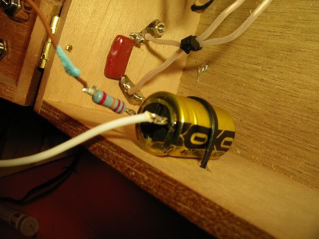
From the RCA signal > 2200uF cap > 22K resistor > board (either side of the board at R1 and R2)

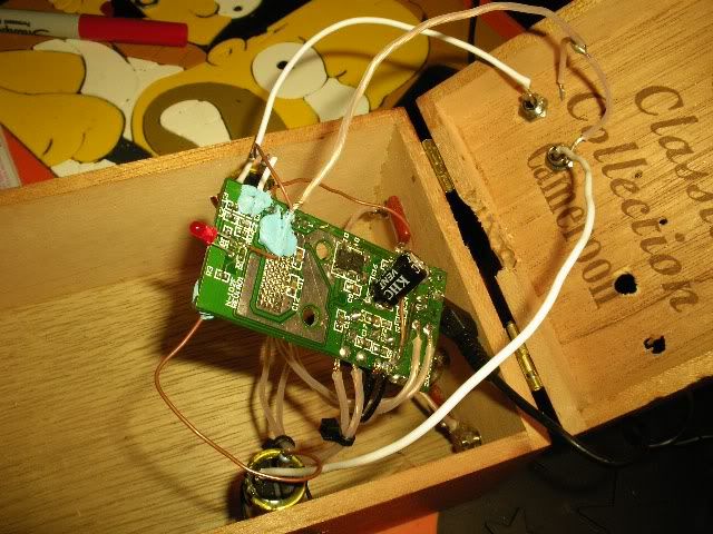
Its hard to get a picture of the whole scinereo.....but I'll try my best to show whats going on.

big picture
IMGP1115.jpg


cap and resistor setup.
IMGP1118.jpg
 
Aug 3, 2005 at 5:24 PM Post #37 of 39
People were reporting 2.2uF was the optimal cap value, I think 2200 is WAY too big as the amp has to charge it up. I can't tell for sure from the pic but am assuming you have the Gnd connected to a Gnd point on the board.

Put a resistor between input and Gnd, using what you have try this (only one channel shown, do for both).

input1.gif


I can't tell what your output cap is either, untill you get it working I suggest sticking with the original caps that were across the speaker output terminals then later swapping in something else.
 
Aug 3, 2005 at 5:59 PM Post #38 of 39
Holy cow.

I think i did it.

but the solder joint on the R1 is so incredibly small that I think I may need to find someone with the right tools to make the connection for me.

i did replace the caps with 2.2uF. They're really really really small. and have a 20% tolerance. is that normal.....

Anyway....

I may just now have on my hands the most fragile poweramp on the planet.

I'll keep you informed.

AND AGAIN, MY UNDYING GRATITUDE FOR YOU'R PATIENCE AND UNDERSTANDING.

BILL
 
Aug 3, 2005 at 6:50 PM Post #39 of 39
Hot DAMN! its good to go!

I cant believe I did it.

If i can do this.......I'm sure that ANYONE can.....with you're all's help of course.
 

Users who are viewing this thread

Back
Top