Anyone want to help me with a T-amp mod?

Aug 2, 2005 at 3:53 PM Post #16 of 39
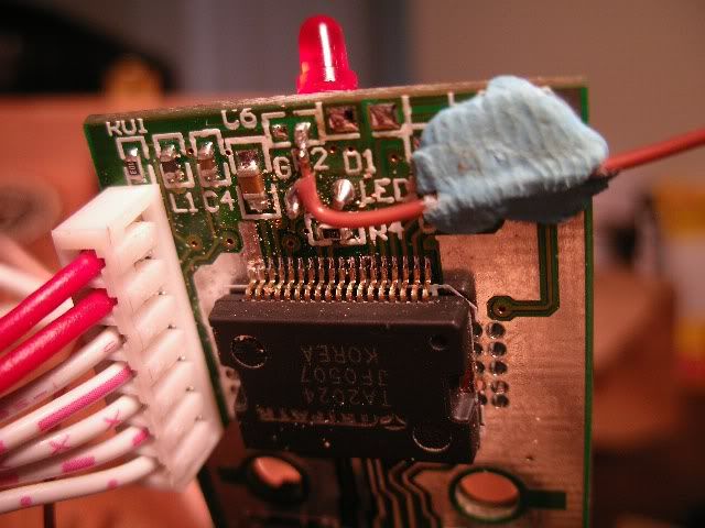
If you do choose to replace the stock input caps and resistors, use fine gauge wire, like 30awg or so, otherwise you'll have a hell of a time getting it to stick to the pad on the board.

The best thing to do, is to get your film cap (2.2-3.3uf), solder the 22k resistor and cap together. They both have long leads on them, so just wrap the resistor lead around the cap lead and solder 'em together. Place the cap/res where you want it in the amp case. The closer to the amp itself, the better. Secure it with tape or glue so it doesn't move around and pull on the thin wire. At this point, you should solder the thin wire to your film cap and then solder the other end to the pad on the board. Do the same for the resistor end and run that to your input connector or appropriate potentiometer tab. Repeat the process for the other channel.

This guy uses Black Gate capacitors in his diagram, but really, film caps are much better than even Black Gates. Even cheap Solen caps from Parts Express are as good or better. The only downside is their size. I don't think that's a big deal for improved sound quality.
 
Aug 2, 2005 at 7:38 PM Post #17 of 39
gawd i feel like such and idiot doing this.

Caps are directional.....which way goes which?

and i had to get a cheaper volume pot, and of couse none of the leads are labeled.

I'm in over my head and my amps in pieces. welcome to my world.

B
 
Aug 2, 2005 at 7:58 PM Post #18 of 39
Cap positive pole goes on the amp side, negative to pot.

Typically (generic?) pots have the adj. lead in the middle, when there are two rows. An easy test would be to turn the pot's shaft 1/3 of the way then measure resistance. The adj (wiper) and either other pole per channel will be lower resistance. Pole-pole will be the rated value of the pot, for example 50K.
 
Aug 2, 2005 at 8:03 PM Post #19 of 39
soldering iron slipped. I may be done for the day with two nice white cauterized stripes down the length of my fingers.

Nah, I'm gonna soldier through this....in immense pain.....this is no longer a hobby. It's a trial.

eggosmile.gif
 
Aug 2, 2005 at 8:35 PM Post #20 of 39
My god. I cant believe i did it. The connection is so incredibly unstable that i have to use superglue to make sure I dont rip the lead off the board. It's ugly as all get out, and I'll post some pics for you all to heckle, but for now, I'm gonna have a beer to counteract the vente coffee I had for lunch......not the smartest idea before doing this.
 
Aug 2, 2005 at 8:58 PM Post #21 of 39
anyone know if bluetac is conductive?

I'm about to cover the solder joints on the board with it to ensure they dont break.....

This is what the connection looks like. i dont want to epoxy it until I know that its a good connection.

IMGP1111.jpg
 
Aug 2, 2005 at 9:07 PM Post #22 of 39
Quote:

The connection is so incredibly unstable that i have to use superglue to make sure I dont rip the lead off the board.


I ended up using epoxy, putting down a thin layer of it (because I'd used magnet wire I wanted to be doubly sure it wouldnt' short against anything while the epoxy set), let the bottom layer harden, then put the wire on that layer and epoxied over it. It then terminated in a bi-pin header. Wish I had a good pic but all I have ATM is this blurry one.

 
Aug 2, 2005 at 9:08 PM Post #23 of 39
Quote:

Originally Posted by ilikemonkeys
anyone know if bluetac is conductive?

I'm about to cover the solder joints on the board with it to ensure they dont break.....


No it's not conductive, but it's not a very good securement either. Have any hot glue? Maybe a drop on a toothpick...
 
Aug 2, 2005 at 9:16 PM Post #24 of 39
this is the only volume pot I could buy locally. The rest of the stuff I canabalized from an old car amp.

any ideas which leads are which? I'm sure these are pretty common.

IMGP1107.jpg


By the way, thank for the help mono. I really appreciate it.

B
 
Aug 2, 2005 at 9:49 PM Post #25 of 39
I"m fairly confident that pot won't work. It looks to be a mono pot (only one channel) plus a switch (the two smaller tabs on the back side).

Presuming you have a multimeter that should be easily enough checked, the two back tabs should open and close circuit between (only) themselves when you initially turn the pot- it might click at that point. As for the longer pins, the center one is usually the wiper. That's all triva for your use though, you need a stereo log pot, somewhere in the 10K-100K neighborhood.
 
Aug 2, 2005 at 10:45 PM Post #28 of 39
Yes, wire the input jacks' L & R directly to two points (for each input channel):

1) 33K resistor going to ground
2) Cap you're adding.

Then wire ground to ground per each channel too.

BTW, you'd be better off with a film cap, in ~ 2.2K value it's not hard to find films.
EDIT: Make that 2.2uF cap, my head was stuck in resistor mode.

However, the 33K is a generic value, you would be better off considering the source's output (input to the amp) to determine the resistor value. If you were using an MP3 player or similar, for example, you might want higher like 50-68K?

Someone else is probably a better advisor on the optimal pull-down resistor value to choose with different sources, as I usually use a POT.
 
Aug 2, 2005 at 11:36 PM Post #29 of 39
I have more solder burns on my fingers than I care to remember. I always find that caffeine usually helps before doing a project -- I make my mistakes when I'm zoning out at the end of a long day.

Is it playing music? Ugly doesn't matter if you can case it back up
biggrin.gif
 
Aug 2, 2005 at 11:48 PM Post #30 of 39
nothing.

I've checked and rechecked everything.

I figured out htat I had to connect the two red wires to make it turn on.......but now i get no sound. Do I have to connect any other wires together?

I really hope I didn't fry it. I love this little guy.


mind that this will probably be my last PCB mod.....this sh!t is way too tiny for my shaky hands to play with.

B
 

Users who are viewing this thread

Back
Top