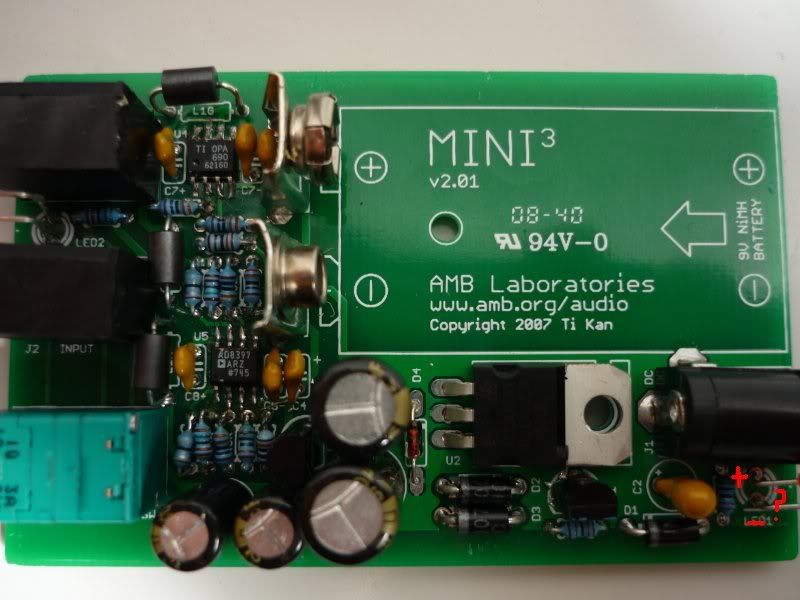
AMB mini3 by hohodiy.com
Mar 30, 2009 at 12:23 PM Post #121 of 163
Thanks again AMB.

When I set my multimeter to "A", OG reads -1.2 and OR reads -4. I have to set my multimeter to "B" and I get a reading of -1124 for OL.

So I guess something is seriously wrong here..? I really hope I haven't damaged my Opamp..
 
Mar 30, 2009 at 12:30 PM Post #122 of 163
Your OG reading of -1.2mV and OR of -4mV are fine. OL at -1.124V is too high.

Remove the battery, turn the power on to let the capacitors drain, and then reflow the solder joints on U5 pins 5 through 7. Reconnect the battery and check the DC offset again.
 
Mar 31, 2009 at 3:06 AM Post #125 of 163
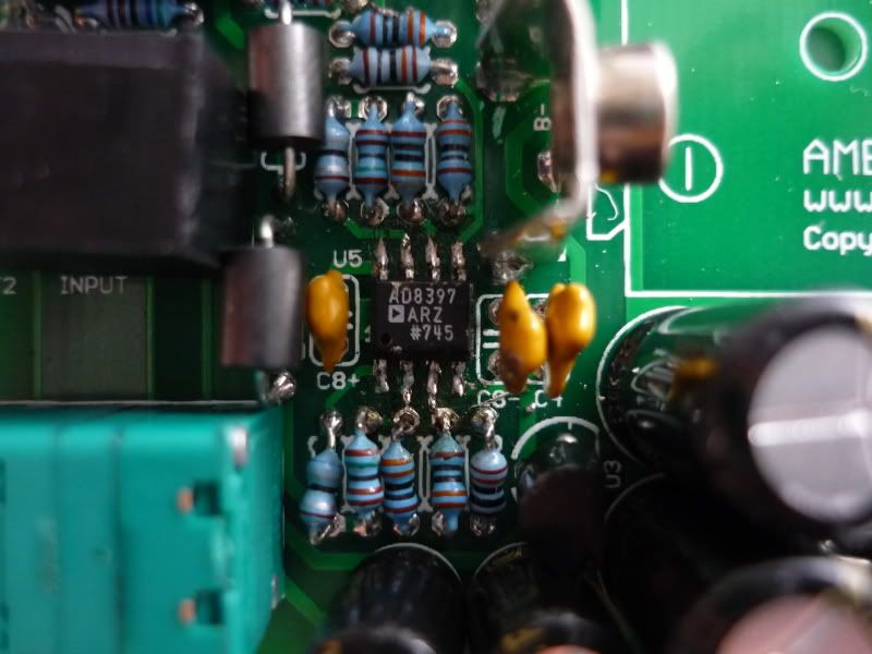
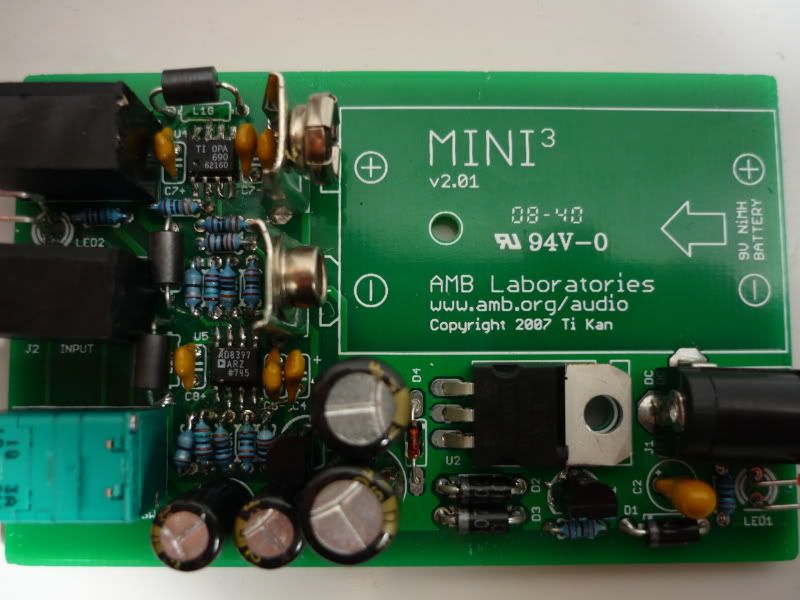
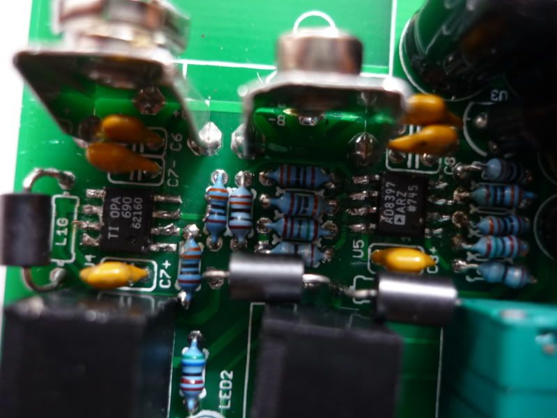
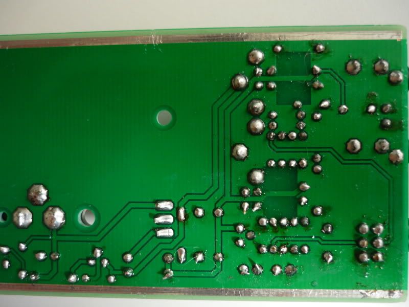
OK I just had a though. With U2 there's a hole for a screw to go through. Does a screw have to be in place for my mini3 to work properly? I have some pictures. Any help would be really appreciated, it's quite frustrating..

P1040199.jpg

P1040208.jpg

P1040223.jpg

P1040213.jpg
 
Mar 31, 2009 at 3:45 AM Post #126 of 163
Ok so I fiddled around with the battery contacts and both channels seem to be working. However, it doesn't sound good at all
frown.gif
Plus after a while i realised U5 was heating up considerably so I quickly turned the amp off..
 
Mar 31, 2009 at 4:12 AM Post #127 of 163
The mounting screw for the 7812 is not required for functionality. It's just there to secure it because the 7812 and the DC power jack also serves as a battery "guide".

Btw, randomly fiddling with the board won't really help you. The fact that your left channel DC offset is high means that that channel is not working properly. You should never have plugged in your headphones because you risk damaging it. If reflowing U5's joint (and the associated resistors) does not correct the DC offset issue, there is a high likelihood that your U5 is blown. Perhaps as a result of the "fiddling around". The Mini³ has explicit warnings about handling of the board while the battery is in place, and about discharging the capacitors after removing the battery. It's a powered circuit and any accidental short circuit to the wrong place could fry the opamps.
 
Mar 31, 2009 at 3:31 PM Post #128 of 163
Thank you for your insight amb, I really appreciate it and I think I have learnt my lesson.

So how should I go about trying to fix it now? Purchase a new opamp and try installing it? Is it possible? I'm a bit daunted because I think it will be quite hard to reach the opamp due to all the other components surrounding it.

How could I avoid this problem in the future? I actually purchased two mini3 kits to build and would dread making the same mistake again..
 
Mar 31, 2009 at 9:46 PM Post #129 of 163
The opamp can be replaced. The easiest way to do it is to simply cut the pins right at where they come out of the opamp (using a sharp Xacto blade) and the remove the opamp body. Then, carefully use your soldering iron to melt the solder on the pads and wipe away the remaining pins. Be careful with the iron so you don't touch the jacks, caps, etc., and burn an ugly mark on them. Use a desoldering braid to soak up any accumulated solder on the pads (be careful so you don't overheat and cause the pads to come off the board).

Then, solder in the new opamp, same procedure as the first time, except now you need to work in a more confined space.

The Mini³ website has all the instructions/warnings/notes that you need. Read and follow them to the letter and you should have success.
 
Mar 31, 2009 at 11:28 PM Post #130 of 163
It also looks like there are possibly some cold solder joints and solder bridges. There appear to be solder bridges from U5 to the nearby resistors, but I think those just duplicate the traces, so they shouldn't be a problem. There also appear to be some solder strings/flecks here and there, which means there could be shorts somewhere.
 
Apr 1, 2009 at 4:35 PM Post #131 of 163
Hey BradJudy, I don't quite understand what you mean by "solder strings/flecks", do you mind elaborating? Which picture do you see it in?
 
Apr 1, 2009 at 8:56 PM Post #132 of 163
chews89 - I mean the stray blobs and splatters of solder I see here and there. They could be bridging or break loose and short out connections. I highlighted a couple in this image:

503539492_EhK5W-L.jpg
 
Apr 2, 2009 at 5:43 AM Post #133 of 163
Thanks BradJudy, I tried to get rid of the excess solder but it still doesn't seem to work. I guess I'll just wait for my opamps to come in.

However, I was thinking of starting my 2nd mini3 build meanwhile. But I thought I should ask some questions first to clarify some things.

Firstly, are my notations in this picture correct? The longer leg of the LED is positive hence it should be positioned so the longer leg goes through the upper hole? So in other words, am I right about which side is positive and negative? Anyone please?

Also I kind of have a dilemma. Should I start building the new mini3 or should I take the opamp of that mini3 and use it on my old screwed up mini3? OR should I wait till my new opamps come in to use on my old mini3?
untitled11.jpg
 
Apr 2, 2009 at 5:52 AM Post #134 of 163
The longer LEG pin is positive (actually, to be pedantic, it's the "anode"). The shorter leg is the "cathode". Cathode is denoted by the line on the board silkscreen.
 
Apr 2, 2009 at 5:57 AM Post #135 of 163
Yes, chews89, normally the longer lead of the LED is the anode (positive) side, while the shorter lead is the cathode (negative) side, often accompanied by a slight "flat" on that side of the LED body.

(amb is too quick...)
 

Users who are viewing this thread

Back
Top