AD 8066 problems
Oct 15, 2009 at 11:46 AM Thread Starter Post #1 of 36

thefallenangelx

100+ Head-Fier
Joined
Jul 16, 2009
Posts
427
Likes
140
Location
Yokohama, Japan
Hi!
ive just made a standard cmoy configuration from tangentsoft tutorial using:

- 470uf power caps instead of the 220uf
- tle2426 rail splitter
- 5.7 gain
- opamp 2170

I just wanted to use a ad8620 (its already on an adapter i made from a thread "diy soic to dip 8 socket" and all the link to the soic opamp pins are ok)
when i insert it in the dip8 socket, the bass sounded really distorted...
I read about decoupling cap so i used 2x 0.1uf caps! and the ad8620 sounded really nice.

So my cmoy became the tangent standard one plus:
- 470uf power caps instead of the 220uf
- tle2426 rail splitter
- 5.7 gain
- ad8620
- dec caps cap 0.1uf

Now, i just wanted to put my ad 8066ar in this cmoy conf...but again the same problem as the ad8620 did before...bass sound distorted...

what should i do to use the ad8066 in my cmoy?

thanx in advance!

Thank you all in advance
 
Oct 15, 2009 at 1:09 PM Post #2 of 36
Quote:

Originally Posted by thefallenangelx /img/forum/go_quote.gif
Now, i just wanted to put my ad 8066ar in this cmoy conf...but again the same problem as the ad8620 did before...bass sound distorted...


... at all levels? With what phones?

AD8066 is a much faster opamp and the decoupling caps must be in close proximity to the opamps power pins, not in a "power section" far away from the opamp.

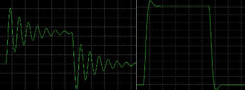
Gain 5.7... Do you use 1k/4.7k resistors? I think there's some serious peaking (at least in LTSpice). If you add a small capacitor (2.2 - 5 pF) in parallel with the 4.7k resistor the square wave looks nicer.

Do you use input resistors? I think you should, and there's no need to use input caps IMO.

When TLE2426 is used to sink/source the return currents from the phones, large caps from rails to ground aren't beneficial. I've noticed that the TLE2426can be unstable with too large caps used this way. Use the caps from rail to rail instead.

If nothing else works you could use a small resistor (10R is often recommended) on AD8066's outputs, or use a zobel network - a cap and a resistor from output to ground, something like 47R and 47nF. Another trick is to use a ferrite bead on the output like Amb does in Mini3.
 
Oct 15, 2009 at 1:32 PM Post #3 of 36
Quote:

Originally Posted by diditmyself /img/forum/go_quote.gif
... at all levels? With what phones?

AD8066 is a much faster opamp and the decoupling caps must be in close proximity to the opamps power pins, not in a "power section" far away from the opamp.

Gain 5.7... Do you use 1k/4.7k resistors? I think there's some serious peaking (at least in LTSpice). If you add a small capacitor (2.2 - 5 pF) in parallel with the 4.7k resistor the square wave looks nicer.

Do you use input resistors? I think you should, and there's no need to use input caps IMO.

When TLE2426 is used to sink/source the return currents from the phones, large caps from rails to ground aren't beneficial. I've noticed that the TLE2426can be unstable with too large caps used this way. Use the caps from rail to rail instead.

If nothing else works you could use a small resistor (10R is often recommended) on AD8066's outputs, or use a zobel network - a cap and a resistor from output to ground, something like 47R and 47nF. Another trick is to use a ferrite bead on the output like Amb does in Mini3.


Every volume!SOny mdr xd200!

The decoupling caps are ok!directly from the v+ and v- pins to the ground!(so the ad8620 worked)

Yep, i use 1k/4.7k resistors!Should i modify the gain?

Input resistors?Where should i put them?
Actually my cmoy refer to the tangent basic cmoy!Nothing more except for the power cap of 470 instead of 220 and the 2 decoupling caps...the rest is the same of tangent's!

What about the small resistor (10R is often recommended) on AD8066's outputs or ferrite bead?
Should i put them from the out pins of the opamp?
Will it decrease compatibility with previous opamp?
 
Oct 15, 2009 at 1:44 PM Post #4 of 36
Quote:

Originally Posted by thefallenangelx /img/forum/go_quote.gif
Every volume!SOny mdr xd200!

The decoupling caps are ok!directly from the v+ and v- pins to the ground!(so the ad8620 worked)

Yep, i use 1k/4.7k resistors!

Input resistors?Where should i put them?
Actually my cmoy refer to the tangent basic cmoy!Nothing more except for the power cap of 470 instead of 220 and the 2 decoupling caps...the rest is the same of tangent's!

What about the small resistor (10R is often recommended) on AD8066's outputs or ferrite bead?
Should i put them from the out pins of the opamp?
Will it decrease compatibility with previous opamp?


Just read this:

Working with Cranky Op-Amps

If you follow that article, your problems should go away.

You could start by lowering the gain to two. If that fixes it, try upping the gain and placing an according cap across R4. (Something like 100pf for 4k7 I guess.)

The AD8066 is the nr1 cmoy opamp, but because it's so fast it oscillates quite easily.

The input resistor referred to is probably R2. If you don't use a pot, you should also run the incoming signal through a resistor.
 
Oct 15, 2009 at 1:44 PM Post #5 of 36
i just tested the ad8066 with my other cmoy...which is the same as the one mentioned here (as diagrams) but instead of 0.1uf dec caps, it has 0.22uf dec caps...but...it doesent work here either!
 
Oct 15, 2009 at 1:50 PM Post #6 of 36
Quote:

Originally Posted by Slash47 /img/forum/go_quote.gif
Just read this:

Working with Cranky Op-Amps

If you follow that article, your problems should go away.

You could start by lowering the gain to two. If that fixes it, try upping the gain and placing an according cap across R4. (Something like 100pf for 4k7 I guess.)

The AD8066 is the nr1 cmoy opamp, but because it's so fast it oscillates quite easily.

The input resistor referred to is probably R2. If you don't use a pot, you should also run the incoming signal through a resistor.


Thank you, ill try to take a look at those...even if im a really newbye to electronic diy.

What do you mean by "across R4 (4.7k)"?

Actuallòy my cmoy doesent have a pot...what bout "should also run the incoming signal through a resistor"?

sorry to bother...and thanx for help!
 
Oct 15, 2009 at 2:06 PM Post #7 of 36
Quote:

Originally Posted by thefallenangelx /img/forum/go_quote.gif
The decoupling caps are ok!directly from the v+ and v- pins to the ground!(so the ad8620 worked)


That's good.

Quote:

Yep, i use 1k/4.7k resistors!Should i modify the gain?


No, the gain is fine. You just need a small cap in parallel with the 4.7k resistor. I think 2.2pF would be perfect.


Quote:

Input resistors?Where should i put them?


You should put them where the input caps, C2, are. Instead of the caps. Something like 220 - 470R. IMO C2 isn't necessary.

Quote:

Actually my cmoy refer to the tangent basic cmoy!Nothing more except for the power cap of 470 instead of 220 and the 2 decoupling caps...the rest is the same of tangent's!


Like I said. It's not beneficial to use large capacitors from rails to ground when using TLE2426 as ground circuit. Read Virtual Ground Circuits

Quote:

What about the small resistor (10R is often recommended) on AD8066's outputs or ferrite bead?
Should i put them from the out pins of the opamp?
Will it decrease compatibility with previous opamp?


There are two ways of using an output resistor. Either like "R5 optional" in the CMOY schematic or outside the feedback loop - between the output of the opamp and headphone jack. I think the latter promotes stability.
attachment.php

 
Oct 15, 2009 at 2:12 PM Post #8 of 36
Quote:

Originally Posted by Slash47 /img/forum/go_quote.gif
Just read this:

Working with Cranky Op-Amps

If you follow that article, your problems should go away.

You could start by lowering the gain to two. If that fixes it, try upping the gain and placing an according cap across R4. (Something like 100pf for 4k7 I guess.)

The AD8066 is the nr1 cmoy opamp, but because it's so fast it oscillates quite easily.

The input resistor referred to is probably R2. If you don't use a pot, you should also run the incoming signal through a resistor.


No, that article is no good. You'll end up with a very noisy amp. There's no need to balance the bias currents when using JFET input opamps.

You should absolutely not place a 100 pF cap across R4! 2.2pF will be fine.
 
Oct 15, 2009 at 2:29 PM Post #9 of 36
The resistors are way too resistant, but other then that you'll end up with a nice opamp rollable cmoy.
 
Oct 15, 2009 at 4:13 PM Post #10 of 36
Quote:

Originally Posted by Slash47 /img/forum/go_quote.gif
Why you would end up with a noisy amp I do not quite see. The resistors are way too resistant, but other then that you'll end up with a nice opamp rollable cmoy.


Johnson–Nyquist noise - Wikipedia, the free encyclopedia

I've tried that circuit. It is noisy. The resistor values are way out of the recommended range. Read the data sheet:
http://www.analog.com/static/importe...D8065_8066.pdf
"Feedback resistances of 300 Ω to 1 kΩ are recommended, because they do not unduly load down the amplifier, and the
time constant formed will not be too low. Peaking in the frequency response can be compensated for with a small capacitor (CF) in parallel with the feedback resistor, as illustrated in Figure 12."

I'm at work now, otherwize I could've simulated how a square wave and the frequency response curve look with different resistor (and capacitor) values. If you're interested I can do it tomorrow night.
 
Oct 15, 2009 at 4:31 PM Post #11 of 36
Quote:

Originally Posted by NelsonVandal /img/forum/go_quote.gif
Johnson–Nyquist noise - Wikipedia, the free encyclopedia

I've tried that circuit. It is noisy. The resistor values are way out of the recommended range. Read the data sheet:
http://www.analog.com/static/importe...D8065_8066.pdf
"Feedback resistances of 300 Ω to 1 kΩ are recommended, because they do not unduly load down the amplifier, and the
time constant formed will not be too low. Peaking in the frequency response can be compensated for with a small capacitor (CF) in parallel with the feedback resistor, as illustrated in Figure 12."

I'm at work now, otherwize I could've simulated how a square wave and the frequency response curve look with different resistor (and capacitor) values. If you're interested I can do it tomorrow night.


To clarify: I agree about that (what's there to agree on, it's a fact) and I hope and believe I also said that (the restors are way too much).

Other then that it's a good reference point about where to place the feedback cap and input resistor etc. And a R3 (cmoy language) of 4k7 should not be a problem.
 
Oct 15, 2009 at 4:43 PM Post #12 of 36
ehm...im lost...anyway helping me in doing a schematic (tryting to preservemost of my values which will works with the ad8066 (leaving the opportunity to use the ad8620 too)?
 
Oct 15, 2009 at 5:03 PM Post #13 of 36
Quote:

Originally Posted by y-factor /img/forum/go_quote.gif
Do you really want to use that AD8066? I never found it to be that good for audio..


yep!i just got two ad8066 so id like to hear how they sound!
then i'll choose which is the best for me, the 8620 or 8066!
but id like to hear before trowing the 8066s away!

If anyone can help me in let the 8066 work with some schematics i would be really thnkful!
 
Oct 15, 2009 at 7:18 PM Post #14 of 36
Yes, I'm aware of the high resistor value problem in the Cranky Op-Amps article. I welcome suggestions for alternate configurations that still meet all the requirements. The main thing is low DC offset with high Iib op-amps even accounting for the variable +IN resistance due to the pot. If you leave the pot out, it's easy to get the behavior you want with low resistor values.
 
Oct 15, 2009 at 8:01 PM Post #15 of 36
so actually i cant get it...should i put the r5 res like 10ohm and will it work?
or should i downsize my feedback resistor (4.7k) to 1k or 2k?
 

Users who are viewing this thread

Back
Top