A47 problem (and my first post) :)
Aug 10, 2008 at 12:29 PM Thread Starter Post #1 of 9

nkko

New Head-Fier
Joined
Jul 23, 2008
Posts
6
Likes
0
Ciao fellow head-fi-ers!
ksc75smile.gif


For some time I was just a lurker here until I gathered some courage and build myself Apheared's 47...

Today I finished it and you can see pic's here:

amp1.jpg

amp2.jpg

amp3.jpg

scheme.png


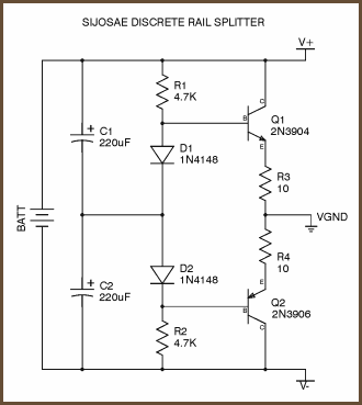
I used Sijosae discrete rail splitter for supply and for the rest I guided myself with Ben Feist's instructions.

I tested few things mentioned in Tangent's guide and everything seams OK.
Current draw is ~50mA and both sides of sijosae splitter are equal.

But on output I have 0,7V (on both channels) if I'm reading it correctly on my el-cheapo analog multimeter?

Oh... I'm using TL072CP, and I have NE5532 which I didn't tryed jet (will it require some mods?)

It sounds bad, it's quite and noisy. Here you can find mp3 that I recorded with mic (I know, I know)... It sounds sustained, tunneled and filtered.... weird.

So... any tips and ideas will help!

Thanks in advance,
Nikola
 
Aug 10, 2008 at 1:09 PM Post #2 of 9
High dc offset means that something is wrong with your circuit.

What is the opamp for the gain stage and the buffer stage specifically?
 
Aug 11, 2008 at 8:49 AM Post #3 of 9
I'm using sijosae rail splitter:
sijosae.png


..and it's working OK for what I understand.

The rest of schematic is completely identical to the one from Ben Feist, only difference is I'm using TL072 (locally available).

Do I maybe need to adjust values of passive components to the different opamp?

Thanks
 
Aug 11, 2008 at 3:01 PM Post #4 of 9
While probably not the best sounding opamp, the TL071 is a JFET input opamp so it should work OK. The 0.7V dc is quite high for DC offset. You are measuring this from ground to L and ground to R I assume? What is the input condition at this time? From my experience, the pot (volume) should be turned all the way down and nothing connected to either the input or output. Also ensure that the 47 ohm resistors are that and not 470 ohm, etc.

I assume that using the Sijosae virtual ground that you are getting a rather even spit on V+ / V-? I've used this circuit before and it works quite well.

Since you used an unconventional layout it is time consuming to check thru it... something that you need to do if you cannot find anything else causing this. Since it the same in both channels, that may make it easier?
 
Aug 11, 2008 at 4:43 PM Post #5 of 9
Today I got a decent digital multimeter, and measured everything once again, without anything connected on it and with pot turned down:

I =~ 53mA
V on splitter is equal and around 7,5V on each side (two cheap 9V)
VoutR = 0,99V
VoutL = 0,96V

I tried to minimize the size with some creative wire bending.
smily_headphones1.gif

I run over everything for so many times it made me see double!
biggrin.gif


I'm without idea what to do?
frown.gif
 
Aug 11, 2008 at 5:16 PM Post #6 of 9
Quote:

Originally Posted by nkko /img/forum/go_quote.gif
Today I got a decent digital multimeter, and measured everything once again, without anything connected on it and with pot turned down:

I =~ 53mA
V on splitter is equal and around 7,5V on each side (two cheap 9V)
VoutR = 0,99V
VoutL = 0,96V

I tried to minimize the size with some creative wire bending.
smily_headphones1.gif

I run over everything for so many times it made me see double!
biggrin.gif


I'm without idea what to do?
frown.gif


So you are seeing +7.5V and -7.5V on pins 8 and 4, respectively of the opamps to ground? And you are certain that you are seeing 0.99V and 0.96V respectively on VoutR and VoutL, and this is not really millivolts (mV)?

For some reason, 53mA seems high for quiescent current draw for a pair of these opamps. From the TI datasheet, I show a max Icc of 2.5mA per amplifier, so that would give you 4 * 2.5 or 10mA. Add LED, etc. to this, as well. I would also guess the Sijosae virtual ground would draw a small amount of current, but 53mA seems wrong, perhaps indicating oscillation. Do the chips get warm or hot at all?
 
Aug 12, 2008 at 12:28 AM Post #7 of 9
Firstly sorry for the fuss!

Problem was trivial and I'm now ashamed.
smily_headphones1.gif


Somehow I forgot to connect pin 6 and 7 on both opamp's!
biggrin.gif

And the weird thing is I just couldn't find it no matter how hard I tryed, It was pure luck....
smily_headphones1.gif


Once again sorry!

But now when it works... I have difference in power rails of 0,1V... I'm slightly loosing it... for the first electronic project it got quite complicated... I'll need to read more.

And the result is lightly put, questionable... Sound is too spacious and lower frequency's are suspended... and not that I just wrote that for the sake... but It really sounds too high and roomy... I'm not liking it at all.
frown.gif


And now I have one more question, as a newb, is it possible not to use potentiometer but the source to control the volume? How great audio compromise is this?

Thanks,
n.
 
Aug 12, 2008 at 1:06 AM Post #8 of 9
Quote:

Originally Posted by nkko /img/forum/go_quote.gif
Firstly sorry for the fuss!

Problem was trivial and I'm now ashamed.
smily_headphones1.gif


Somehow I forgot to connect pin 6 and 7 on both opamp's!
biggrin.gif

And the weird thing is I just couldn't find it no matter how hard I tryed, It was pure luck....
smily_headphones1.gif


Once again sorry!

But now when it works... I have difference in power rails of 0,1V... I'm slightly loosing it... for the first electronic project it got quite complicated... I'll need to read more.

And the result is lightly put, questionable... Sound is too spacious and lower frequency's are suspended... and not that I just wrote that for the sake... but It really sounds too high and roomy... I'm not liking it at all.
frown.gif


And now I have one more question, as a newb, is it possible not to use potentiometer but the source to control the volume? How great audio compromise is this?

Thanks,
n.


It is of course possible to use the source to control the volume, but that means you are listening out of a headphone jack. The idea of the headphone amplifier is to bypass the amplifier stage inside the device (iPod, etc) and use the line out to run to your amp. This is when the potentiometer becomes very handy, as line outs generally are not volume controlled.

Hope this helps (also, what are you listening out of?)
 
Aug 13, 2008 at 9:11 AM Post #9 of 9
Currently I have iPod shuffle (1st gen) and some Sony CD walkman... both don't have line out...

...now I'm pondering on designing cheap black box with minimal parts to put in between source and phones to act as flavoring device.
smily_headphones1.gif
Just for fun!
 

Users who are viewing this thread

Back
Top