At the risk of drifting off thread, digital audio is a complex business largely because brickwall filters do not perform well in the time domain, as has been realized. An acquaintance of mine in professional recording told me 25 years ago that the first DAT machines were not transparent at all in his opinion. Opinions vary, but I agree with him.
As compaired to what? An analog tape?
If you want to compare anecdotes, I worked at a professional studio back when digital audio was very, very young. Once, by accident, our monitor source was the return from a digital audio recorder instead of the 2-mix bus of the console. It stayed there for a very long time and nobody, none of us, including our young hot-shot engineer with golden ears, knew the difference! We were listening, in effect to a complete record/play cycle through ADC and immedately through DAC. And that was in the days before oversampling filters, and 44.1kHz sampling frequency.
Funny thing....analog tape never fooled anyone like that.
How's that?
Even 192/24 is not transparent on a setup I heard.
Again, as compared to what? Did you have a live analog source to compare to?
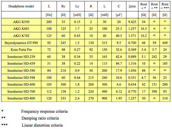
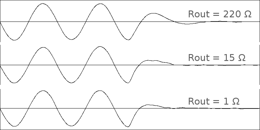
The corollary of brickwall in the frequency domain is temporal smear, although this should be less of a problem with higher sample rates.. Meridian are attempting to rectify this with MQA. There's also an interesting graph of impulse response on this page:
https://www.plusmusic-us.com/index.php/technology/sla/dynamic-vs-sampling
....And the marketing hype again raises it's ugly head. Are you aware that Meridian coined the term "temporal smear", and that there's not a single shred of scientific proof that it's audible?
I think the total system impulse response is of very high relevance to sound quality.
Sure...but correlation of impulse response to audibility is a total mess.
The ADC/DAC system including the filtering and any rate change interpolation is a big part of that, as obviously is the headphone or speaker.
One of these things does nothing to the reproduced sound, the other changes it radically. Care to guess which is which?
I think quality sound is less about the >20KHz bandwidth and more about abrupt frequency domain behaviour with its time domain implications.
Ever seen an impulse response, or any time-domain data on analog tape recorders? No? I have. They're a hot mess, just a different one. They are NOT free of time domain issues at high frequencies by any means. In fact, don't bother with impulse response, just try to reproduce a square wave...any frequency you like, using analog tape. Take a look at it on a scope, you'll see a very interesting wave form...but not a square wave! It'll tilt, ring and overshoot, and worse, be unstable over time.
Research into the audibility of nonlinear phase shift has shown it has to be massive...many times that of any antialiasing filter, or reconstruction filter...to be audible.
It's all what you compare to. And yes, this should pretty much drift off thread...