A Very Compact Hybrid Amp
Dec 8, 2010 at 10:40 PM Post #2,131 of 2,218
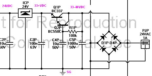
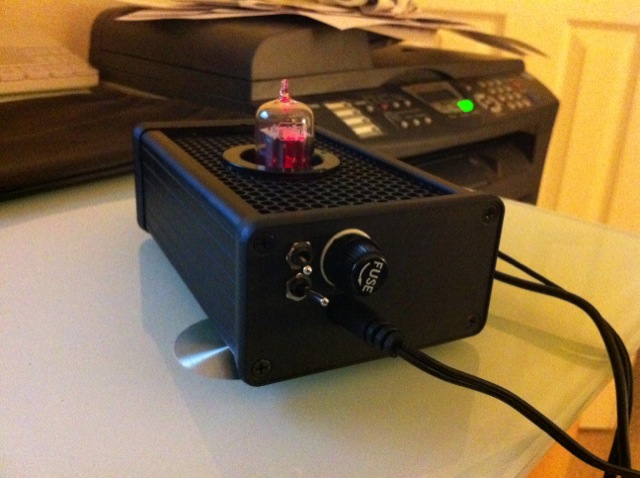
You should be able to add more resistance to the LED wiring, if it's of concern to you.  FWIW, I use a single LED and when the "red" is on, the LED is brighter.  When off, it's lower.  Details on that, hmm, I can't quite remember and I don't want to open up my case.
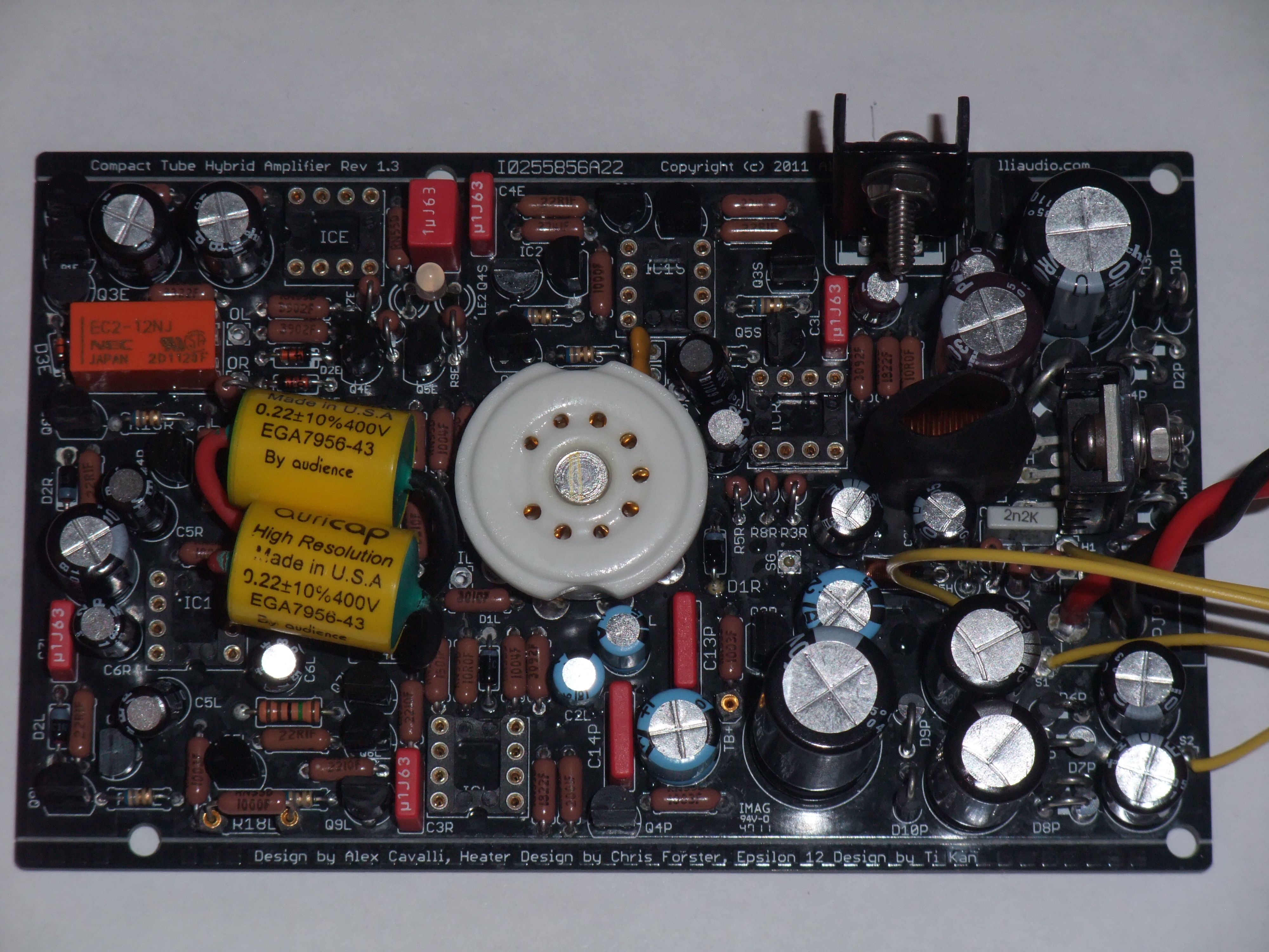
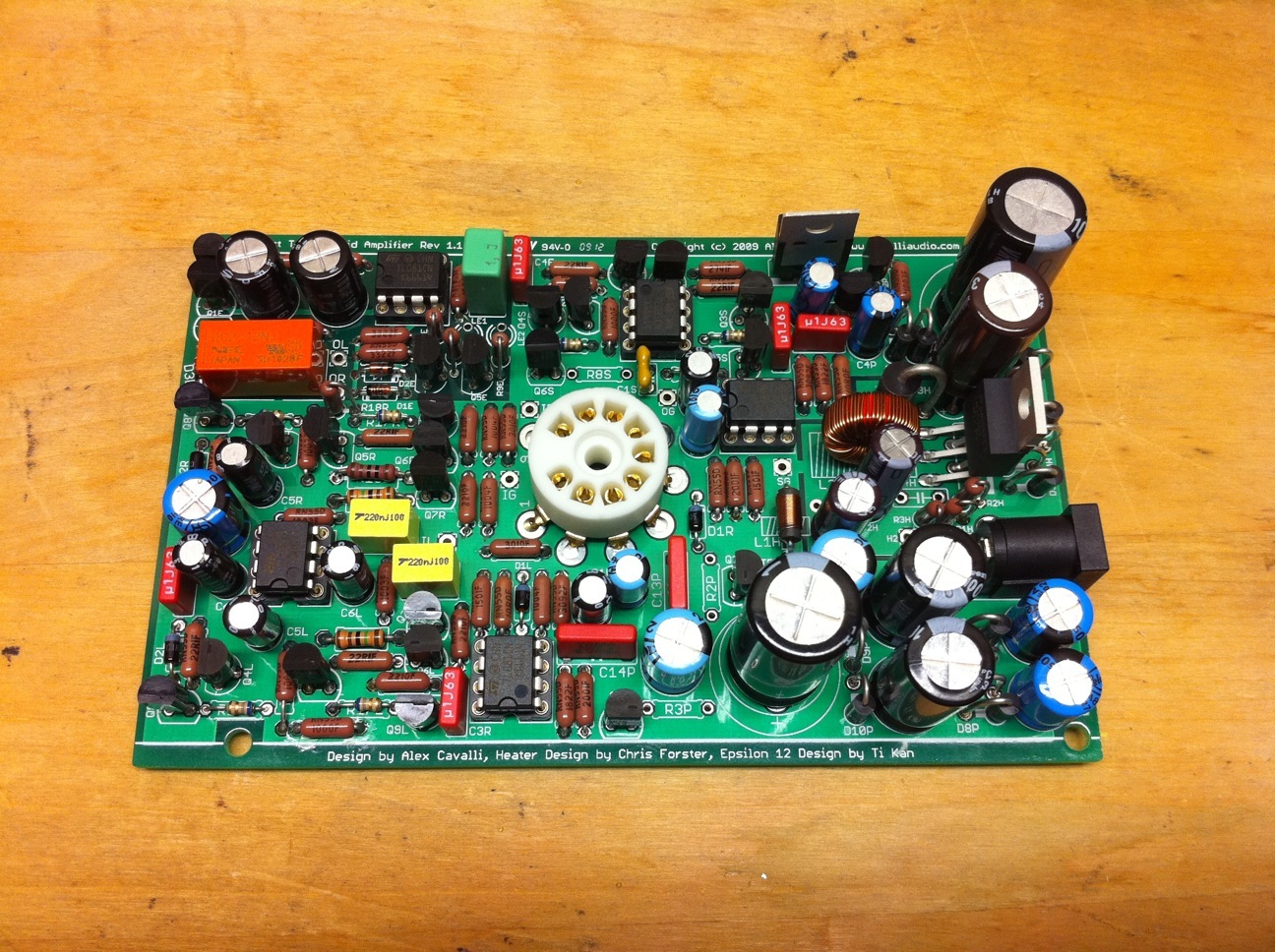
 :p
 
Dec 9, 2010 at 8:09 PM Post #2,132 of 2,218
Quote:
We want inside pics!!\

And here you go:)   Since my 1st post of the 1st CTH proto PCB up & running had a playing card next to it, thought I'd do it again:


As a heatsink fan I decided to move my 24V reg out of the case & on to that top heatsink (note: it is absolutely not necessary to do this, an internal reg + heatsink + vent holes is fine). 
It's mounted w/its metal tab up on one of the 2 screws.   Working fine w/the short wires you see here (note heatshrink):


Since the 1/4" stereo side jack went in the PCB no longer slides nicely out the back... Access is now by popping the ends, pulling the sides of the hammond case outward & popping up the lid (partly due to short 24V reg wires).  The TO92 paddle heatsink on my BC550 Q1P coupled w/the LV reg's heat outside the case has probably helped be avoid the change to BC337 there... I use it at least 15 hrs/week.


Dec 12, 2010 at 3:35 PM Post #2,136 of 2,218
My CTH has been running for a few months and it worked perfectly except for a slight hiss. Today I tried to fix that by replacing the in and output wires with some shielded cable. When I turned it back on there was a loud hum. I tried multiple tubes and nothing changed. I've redone the initial checks and the results are: OG/OL/OR to SG 12.01V,  TB+ to SG 95V, tube pin 1 to pin 6: 00.4 and the e12 trips as soon as the probes touch the pins. My guess is that the tube opamps are blown. Am I correct?
Also do I have to raise or lower the value of the output resistors to reduce hiss with low Z phones?
 
Dec 12, 2010 at 3:41 PM Post #2,137 of 2,218
Pin 1 and 6 need to be measured with respect to SG. 
 
And when measured wrt SG, they should be identical. Also did you make sure you grounded the shield only on the source end?
 
Dec 12, 2010 at 3:50 PM Post #2,138 of 2,218
Pin 1/6 to SG is 90.5 and 90.7, The wire is 2 conductor +shield so the shield is the ground conductor. 
 
 
EDIT: nvm, I had IR and IG reversed. My CTH works now and is playing sweet music
 
Dec 12, 2010 at 8:01 PM Post #2,139 of 2,218
>  Also do I have to raise or lower the value of the output resistors to reduce hiss with low Z phones?
 
You raise the R18s.. Default is like 60R->100R & IIRC max of 120R->150R for them(?).
 
Dec 13, 2010 at 1:41 PM Post #2,140 of 2,218
Interesting cf, I woulda thought you would mount the reg to the inside of the lid for shorter wires.
 
Heres a little double LED video action....
 
http://www.youtube.com/watch?v=Kyf9LKy2TXQ
 
Dec 13, 2010 at 4:52 PM Post #2,141 of 2,218
Quote:
Interesting cf, I woulda thought you would mount the reg to the inside of the lid for shorter wires.

 
Yeah, that would be easier all around too (you could unscrew to get reg free, mine's pretty soldered).
 
IIRC I did it this way because the very 1st rendition was using the case as a heatsink (reg was mounted to case bottom/underside of PCB) & I didn't like the way the whole case heated up.
Note:  again I've experienced no problems w/the length wires you see.   Maybe you'll come up w/a smarter way:)
Quote:
forsakenrider said:
/img/forum/go_quote.gif

Heres a little double LED video action....

Heh, it looks like you said @ startup - RED is bright (as it should) & GREEN is dim (& should be "off"),  then @ latch its all good (RED off, GREEN on).
My guess would be questionable BC560(s) in the "light" circuit OR you have to play w/LED resistor values, as holland suggested, to get things looking as expected during startup.
IMO the dual colors have a nice, seasonal look to them & it could take a lot of fooling around to "fix"... And we don't like "unnecessary" surgeries:)
 
Dec 13, 2010 at 8:45 PM Post #2,142 of 2,218
This is happening because the base current in Q5E is flowing through the LED. You can reduce the base current by increasing R8E without harming the circuit. Try something like 330k or even 470k to see if this fixes the problem while still lighting the green LED bright enough when it's on.
 
Jan 3, 2011 at 12:00 PM Post #2,143 of 2,218
The LED doesnt really bother me, I kinda like it like that anyway....
 
BUT! since changing to the BC337 it seems like my e12 trips WAY too easy. I try not to listen to music thats part of the "loudness war" so sometimes at listening volume there will be a loud kick drum or something and POP! trips the e12. Did the values change since the proto? I remember getting lost in the music not long after and "if it aint broke don't fix it" when there was little changes.
 
Jan 3, 2011 at 1:28 PM Post #2,144 of 2,218
Jan 3, 2011 at 1:35 PM Post #2,145 of 2,218
Double check that your power rails, after the BC337 change, is not fluctuating and actually regulating.  Something may have been damaged during the swap.  A fluctuating 24V will likely trip the e12.  Try a different tube also, just to rule that out.
 
Other than the tube, I'd suspect something went amiss during the swap.  I can't recall if you swapped the regulator, but it may not be operating within it's designed parameters.
 

Users who are viewing this thread

Back
Top