A Very Compact Hybrid Amp
Jan 8, 2009 at 2:50 AM Thread Starter Post #1 of 2,218

runeight

Member of the Trade: Cavalli Audio
Joined
Oct 10, 2002
Posts
2,941
Likes
1,422
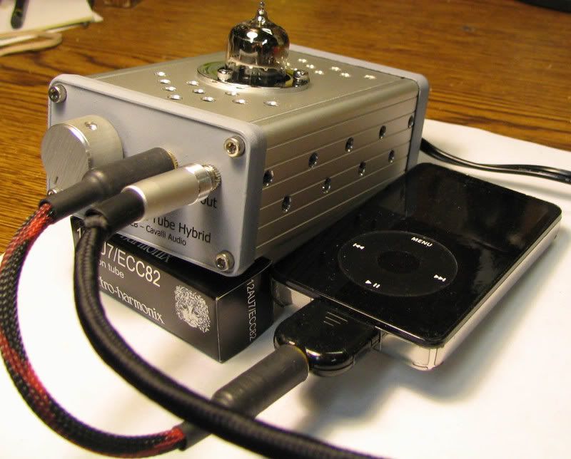
Hello everyone. After much background work and some fair amount of prototyping cfcubed and I (with some help from forsakenrider) would like to introduce a very small hybrid amplifier.
This amp was born out of cfcubed\'s efforts to make a teeny tiny hybrid amp as discussed in this thread,

Teeny Tiny Tube Amp

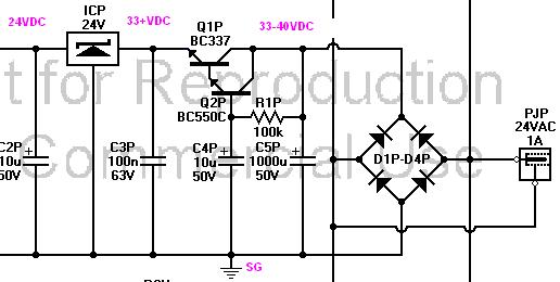
cfcubed wrote to me about this idea and, as it turned out, I had been working in the background on a small hybrid that could be powered from a walwart. In this case, however, I wanted the tube to have a higher plate voltage than is available in other hybrids so I had already determined to use a SOHA II voltage multiplier.

As we discussed what the design goals were we came up with these:

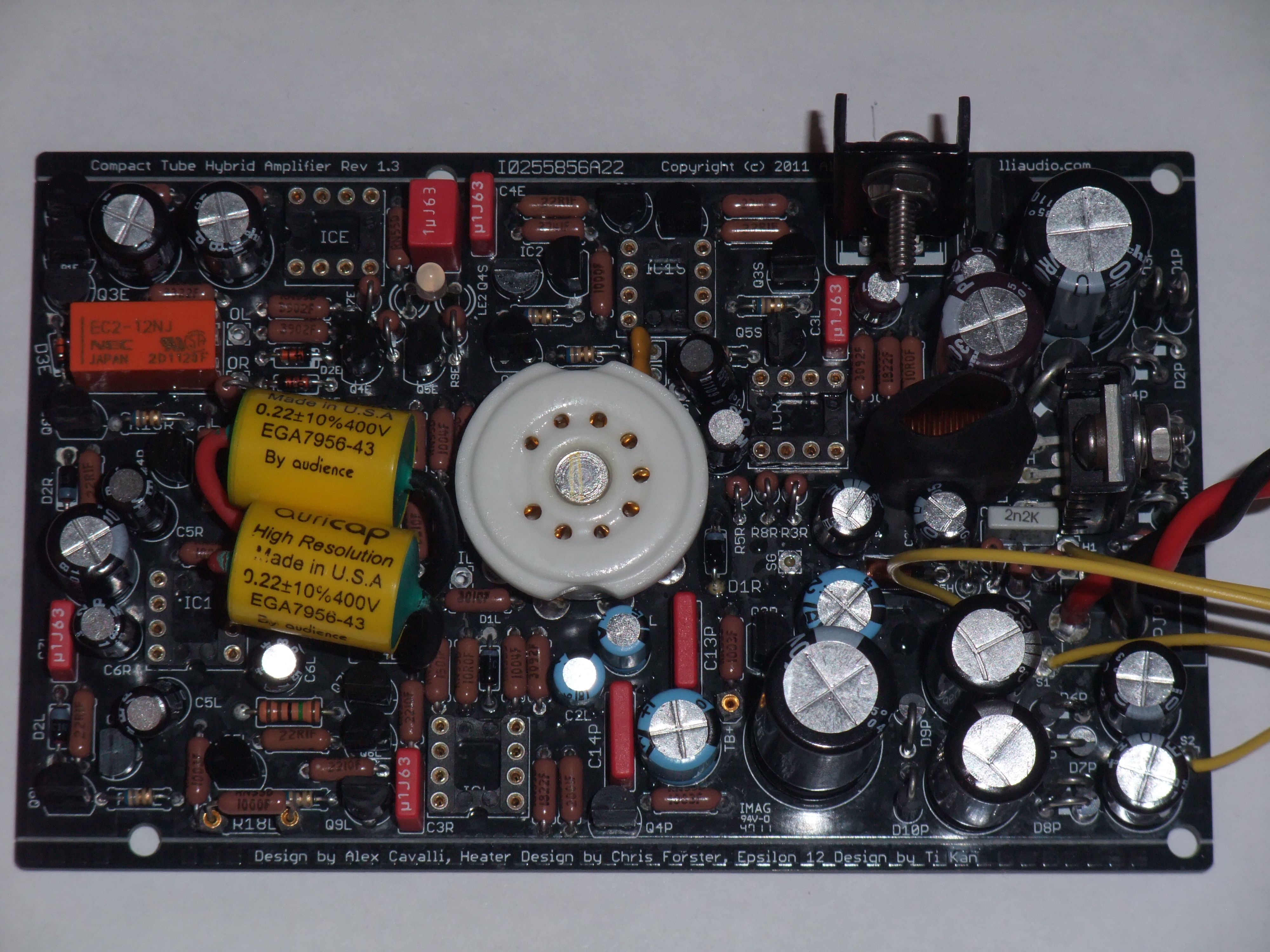
1. Fit on a 75mm x 120mm board to slot into a hammond enclosure.
2. Use discrete output buffers.
3. Elminate the trimpot as used in the SOHA
4. Generate high than 40V for the tube
5. Use a buck regulator for the heater supply
6. Include AMB\'s e12

It took a while to satisfy all of these requirements, but at this point, after a POC build by cfcubed and some small prototyping by runeight, we think we have a nice little amp. I want to thank cfcubed for all of his great ideas, collaboration and time and prototyping work.

cfcubed will be filling in on some of his builds and experience and, in particular, his heater circuit design. And anywhere else that he feels like it.

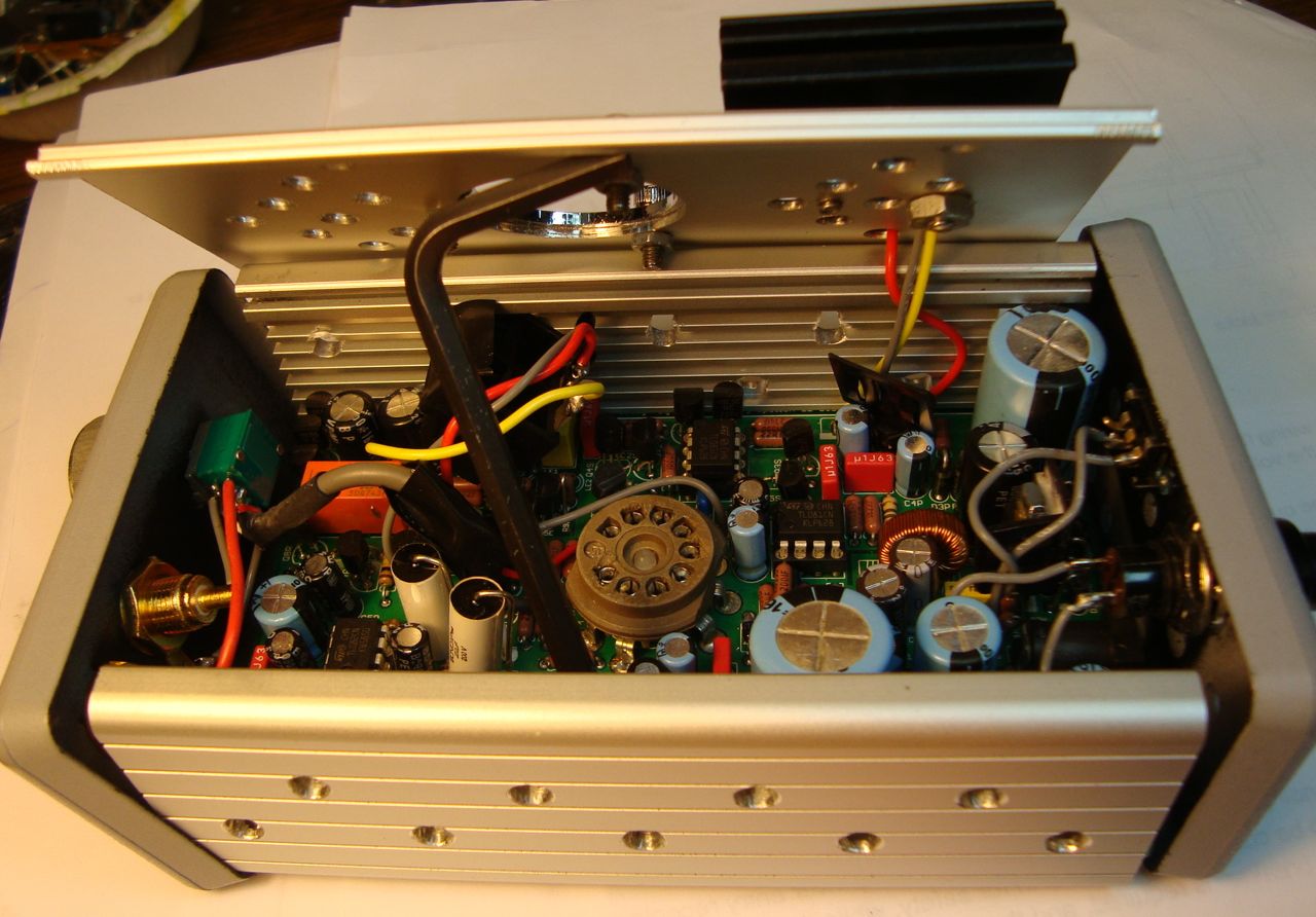
I\'ll be posting each section of the amp with an explanation in follow up posts. We have a board design which is at the fab right now waiting to make a small prototype run. There are enough boards for others to build a proto if you have an interest. Please let us know.

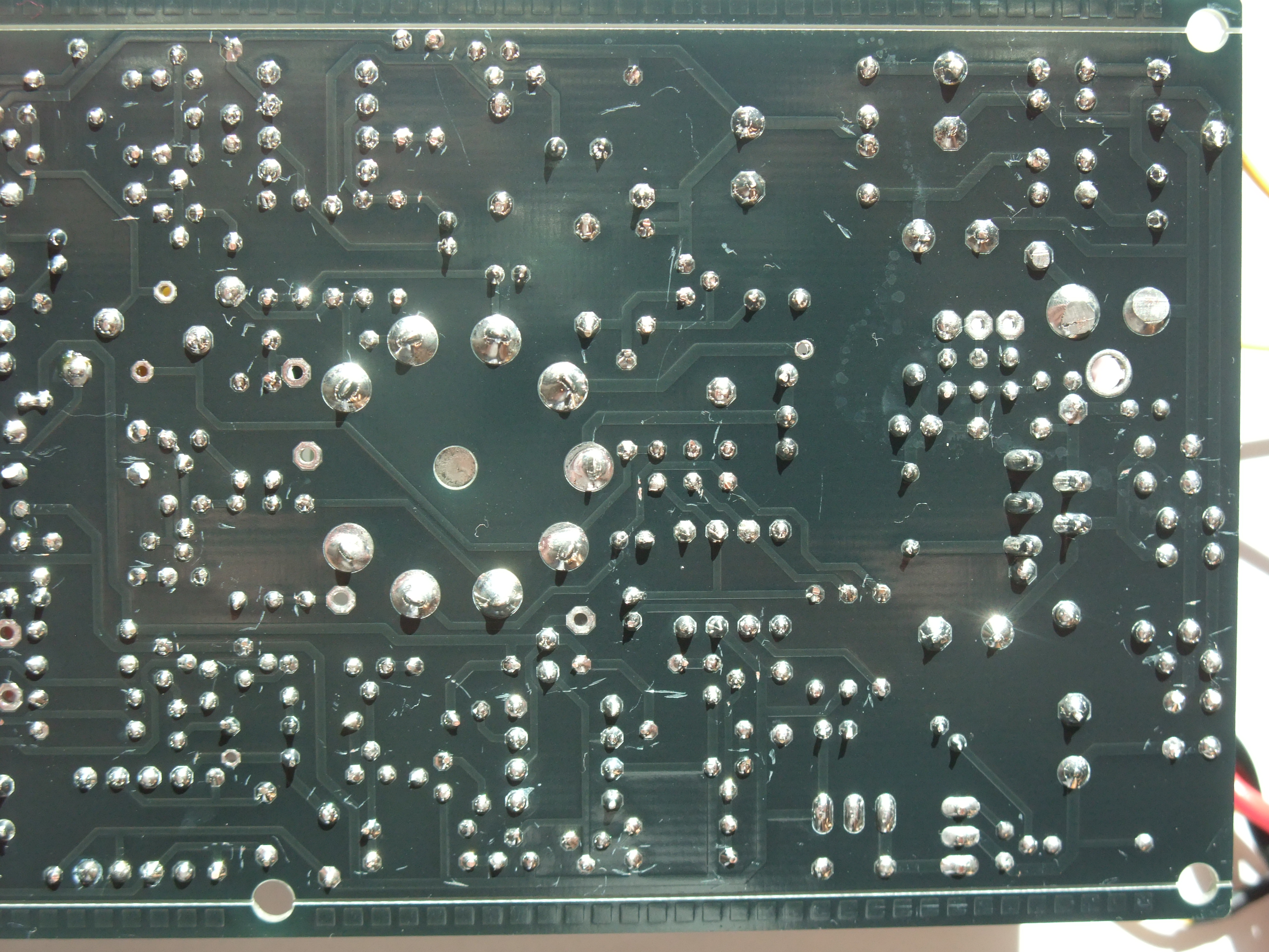
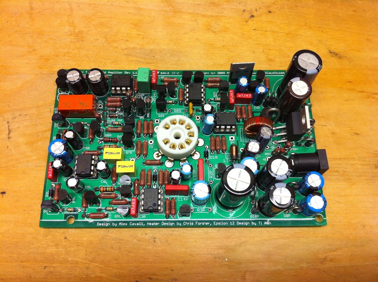
For now I\'m posting a 3D image of the board and a PDF of the PCB. You can print the PDF at scale to see just how much stuff is crammed onto this board and how tiny it is.

Compact Hybrid Board

Here\'s the 3D:

attachment.php

 
Jan 8, 2009 at 3:20 AM Post #2 of 2,218
As from HW, yes this project evolved quite a bit from my original (but not so original
smily_headphones1.gif
concept in that "Teeny, tiny, tube hybrid.." thread.

Initially, I was looking for a transportable tube hybrid that would meet or exceed original SOHA performance with size allowing it to fit in a briefcase. Thought that meant using a pencil tube. Wanted muting delay & to avoid SMD construction. dBel84 and PRR made very constructive comments (esp. PRR pointing me in the direction of switchers). Upon contacting runeight, found he was thinking about the same sort of project.

With runeight's continual pushing of the envelope (no pots, discrete buffer, etc), what we appear to have now is a mostly no-compromise implementation on a PCB smaller than a 3" by 5" index card. And in a case that fits on your hand http://www.hammondmfg.com/pdf/1455K1202.pdf (albiet, requiring a 24VAC 1A wallwart). Idea is that one could have $20 wallwarts at home & the office and just transport the amp.

The project offers a good deal of tube rolling possibilities (e.g. 6.3V / 12.6V switchable heater supply - my little design contribution
smily_headphones1.gif
and the only hot device in the case should be the tube.

There is some compromise, of course, to fit in essentially a 3"W x 5"L x 1"H space (component selection comes to mind, e.g. pots, caps, jacks must adhere to clearance restrictions) and it is still a one-tube design. If the current success we're experiencing with the amp hold, its cost & performance should fall between full SOHA & full SOHA II builds (builders/listeners deciding where the performace lies).

So we are currently looking to building out a few prototype PCBs (the 1st BoM is nearly complete)... With 400+ holes to fill on a tiny board, prior build experience would help & of particular interest to me would be qualified SQ judgements.

Attached is a pic of the last POC for the project (has 250v comps in HV instead spec'd 100v)... There are a few minor devations from the current state but with exception of the "pot-less" tube stage, all the individual circuits are in this POC & sound good to me
smily_headphones1.gif


All I can say now is whew
smily_headphones1.gif
Thumbnail of POC:


Feb 23, 2009 update: CTH proto PCB stage nearing completion... My CTH is done & I'm liking it:

cth_done_ipod.jpg


Tube rolling possibilities here.

Features, etc worded in another way.

March 16th, 2009 update: CTH Design, etc. link available on Cavalli Audio, PCBs, kits available...
In addition to all the info + reviews in this thread, there is now a CTH kit thread too.
 
Jan 8, 2009 at 7:22 AM Post #3 of 2,218
I would be very interested in building one of the prototypes. I've built 2 Starving Students, 2 YAHAs, and will probably build a slightly modified YAHA as soon as my Mouser order arrives. My orthos love hybrid amps.
smily_headphones1.gif
 
Jan 8, 2009 at 10:22 AM Post #4 of 2,218
The Buffer

Using an off-the-shelf walwart necessitated some important design constraints. And working within 75mm x 120mm necessitated a few others.

Some hybrids use DC walwarts. This is the simplest way to supply DC power to the amp but it tends to limit the B+ to something less than what the walwart can supply.

However, if we use an AC walwart, as is used in other hybrids, then we have the opportunity to use voltage multipliers to create a higher B+. How high depends on the voltage from the walwart and the number of stages in the multiplier.

In this case I had settled on a 24VAC walwart as the starting point. There is an additonal limitation imposed by using a walwart. Since the walwart only supplies two wires there is no CT. And with no CT we cannot create a split supply for a complementary output stage. We could use an SE output stage as in the SOHA II but the power requirements for this are too high.

So, the two constraints of small space and AC walwart power require that the O/P stage be:

1. Complementary
2. Use TO92 size devices
3. Use a rail splitter to avoid using a large output capacitor

Number 3 further means that, since the O/P is direct coupled to the headphones, it has to be a self-zeroing buffer. This is because the buffer will be coupled to the tube stage by a small coupling cap.

After some thought, this is the buffer that we settled on:

SCHABuffer1.00.gif


This is a fairly conventional diamond buffer. The O/P devices are the BC327/337 complementary pair and the input devices are the BC550/BC560 pair. These are all TO92 devices. The operating point is rougly 20mA in the O/P. Since each device sees about 12V this makes for about 240mW power dissipation for these 600mW devices.

The top input device is loaded with a CRD to establish the current in the input stage. The bottom devices is loaded with an opamp controlled current mirror. The opamp/mirror control the offset. There is enough range in the servo to account for most device variations. In this case the complementary devices should be from the same hfe class to minimize any possible problems. For example, BC550/560 should be "C" class and the BC327/337 should be "25" class.

Notice that the opamp reference voltage is not "ground" but the virtual ground that will be coming from the splitter (VG).

cfcubed has proto'd this buffer with the splitter (next installment) and the servo is able to maintain very good, small DC offset.

Since this is a complementary buffer it can go into class AB mode. And while it can't make as much power as a buffer with power transistors it can make enough to power most headphones.

Two of these buffers, obviously, are on the board sharing a dual opamp for the servo.

R18 is an optional output resistor to make it easier to control the gain for the wide variety of headphones that can be used.

Next stop is the rail splitter.
smily_headphones1.gif
 
Jan 8, 2009 at 11:20 AM Post #5 of 2,218
Nice work Runeight and Cfcubed! Should make some great sound, based on your other work. :wink:
 
Jan 8, 2009 at 5:49 PM Post #7 of 2,218
The Splitter

Because the rail splitter sources and sinks the currents in the O/P stages, the "SQ" of the splitter is almost as important as the SQ of the buffers themselves. And so we decided to make the rail splitter look as much like the buffers as possible. This meant a discrete rail splitter with opamp control.

Like this:

SCHASplitter1.00.gif


This splitter is essentially an opamp driven diamond buffer, very similar to the O/P buffers. Except that here the opamp is allowed to operate at AC so that it will keep the O/P of the splitter at the VG point set by the TLE2426.

This type of splitter is not new or unique, but it is very compact and it works very well in this amplifier.

Next, the Input Stage
 
Jan 9, 2009 at 12:24 AM Post #11 of 2,218
ludoo and MrSlim I'm waiting on proto boards right now. But we'll keep you guys up to speed as things progress.

digger945, the original teeny tiny amp that cfcubed was working on used pencil tubes. However, we were able to make this amp so small with 9 pin miniature tubes that we didn't really need to use the pencil tubes to space. And doing this means socketed tubes and tube rolling.

Since cfcubed's heater circuit is switchable between 6.3V and 12.6V any of the 12au7 class or 6922 class of tubes should work. I'm expecting that other tube types will work as well. But we'll have to experiment.

The link doesn't work for me either. I think because headwize is down for upgrades at the moment.
 
Jan 9, 2009 at 1:09 AM Post #12 of 2,218
Quote:

Originally Posted by runeight /img/forum/go_quote.gif
digger945, the original teeny tiny amp that cfcubed was working on used pencil tubes. However, we were able to make this amp so small with 9 pin miniature tubes that we didn't really need to use the pencil tubes to space. And doing this means socketed tubes and tube rolling.


Yes, it became clear during development that it was not desirable to limit the amp to pencil tubes. If there is demand for it, it is possible in a future rev of the board to re-route a couple traces that pass under/within the 9-pin "circle" so that a .5" hole could be drilled in the center. This would allow tubes like 6N16B (shown in POC) & 6111 and others to be recessed within a grommet within that hole & soldered in and likely avoid any protrusion above the top of the target case.

I may DIY one-off pencil tube -> 9-pin socket adapters to compare such tubes to the 12AU7 variants I have on hand... If a 6N16B or 6111 were by chance my favorite in the amp I'd send a request to runeight
smily_headphones1.gif


Quote:

Originally Posted by runeight /img/forum/go_quote.gif
The link doesn't work for me either. I think because headwize is down for upgrades at the moment.


Uh, umm, that thread is a bit embarrassing for me anyway... Let's just say I've learned quite a bit in the last several months (esp. about switchers
wink.gif
) I will have a bit of info in the next few days about the SM heater implementation that was necessary for heat & size restrictions... It seems an ideal choice in this case especially with the higher freq part & secondary filtering we've implemented.
 
Jan 9, 2009 at 4:11 AM Post #13 of 2,218
Input Stage

As most of you know by now, one of things I didn't like about my orignal SOHA design was the trimpot. This problem is solved nicely in the SOHA II with an input stage that permits a small amount of feedback which, in the SOHA II, really helps with tube rolling and gives excellent performance.

However, in this amp we don't have room for the nice front end in the SOHA II that needs two tubes. We can only have one tube.

So how do we set the plate voltage for the tube without loading it down too much (destroying the high frequency response)?

Like this:

SCHAInputStage1.00.gif


The triode is set up, more or less, as a simple grounded cathode amp with a CCS plate load and a capacitor bypassed cathode resistor.

The opamp is wired so that it simply adds or removes a small amount of current into the cathode circuit to set the plate voltage according to its reference. In this design we've taken the reference, not from the B+, but fromm the V+ because the V+ is regulated and, presumably, steady. Since it's a constant voltage we can use a simple resistive voltage divider for the reference (18k/2k). Using the regulated V+ for the reference also makes the servo mechanism much more immune to changes in the B+ that may be caused by line voltage variations.

The 1M/33k divider samples the plate voltage. The resistor ratios are set so that with V+ = 24V the opamp will try to set the tube's plate to 75V. It will do this independently of which tube is used so long as the tube can come to an operating point with the current in the CCS, 75V on the plate, and a cathode bias that is more positive than the grid. This will be quite a few tubes.

The 1k5 cathode resistor is there to pass as much of the cathode current as possible to keep the opamp out of the signal path (the exact ratio of currents, however, depends a lot on the tube in use). The cathode bypass cap helps further with this when signal is applied. In addition, even though the plate load is a CCS so that the cathode current is nearly constant, the cathode bypass cap lowers the Zo of the stage giving better bandwidth for a given load.
'
The 1M resistor attached to the plate is a very high load. It will be in parallel with the Zi of the buffer which is also in the megaohms range. Thus the tube sees the high load resistance that we need for good performance.

The CRD is used here (and in the buffers) to save space. There is no room for fancier CCSs in this amp.

Next, a new twist on AMB's E12
 
Jan 9, 2009 at 4:44 AM Post #14 of 2,218
Runeight.. thanks for the info.. This looks like its going to be a cool little unit.. It'll only be a little bit bigger than the CuteBatteryII I have on my desk now....
Looks like Headwize had a server crash and they are in recovery mode(all the data is ok though..)
 
Jan 10, 2009 at 4:28 PM Post #15 of 2,218
An E12 with Lights

Although it's not absolutely necessary to have offset protection on direct coupled amps, it seems to me this is always a good idea. O/P stages like the one here and in other amps rarely fail but when they do, well . . .

AMB's E12 is a very tiny, but effective circuit. So we have adapted it to this amp. In fact, it's even smaller here because cfcubed insisted on using a smaller NEC relay whose pads are on 0.1" spacing (see the pdf).
smily_headphones1.gif


And then we added lights. This idea came from a request by Uncle Bob on the SOHA II Builder's thread asking if there was a way to put some kind of indicator light on the E12.

Here it is:

SCHAE121.00.gif


This E12 has slightly different timing and threshold from the original. It will trip at about 120mV and trip a little slower than the orignal.

The lighting circuit lights green when all is well and lights red when the relay opens for any reason, either during startup or because of an offset.

If you build this, you'll be able to use a dual LED that you can insert under the tube socket. This LED then can light the two colors through tube telling you what condition the O/P is in.

We did this because we can't help it . . .
smily_headphones1.gif


The next installment will be cfcubed's description of the heater circuit. After that it's time to proto on the new boards.
 

Users who are viewing this thread

Back
Top