


aphexii
500+ Head-Fier
- Joined
- Oct 14, 2005
- Posts
- 723
- Likes
- 11
Wow, I must be half asleep today. My bad.
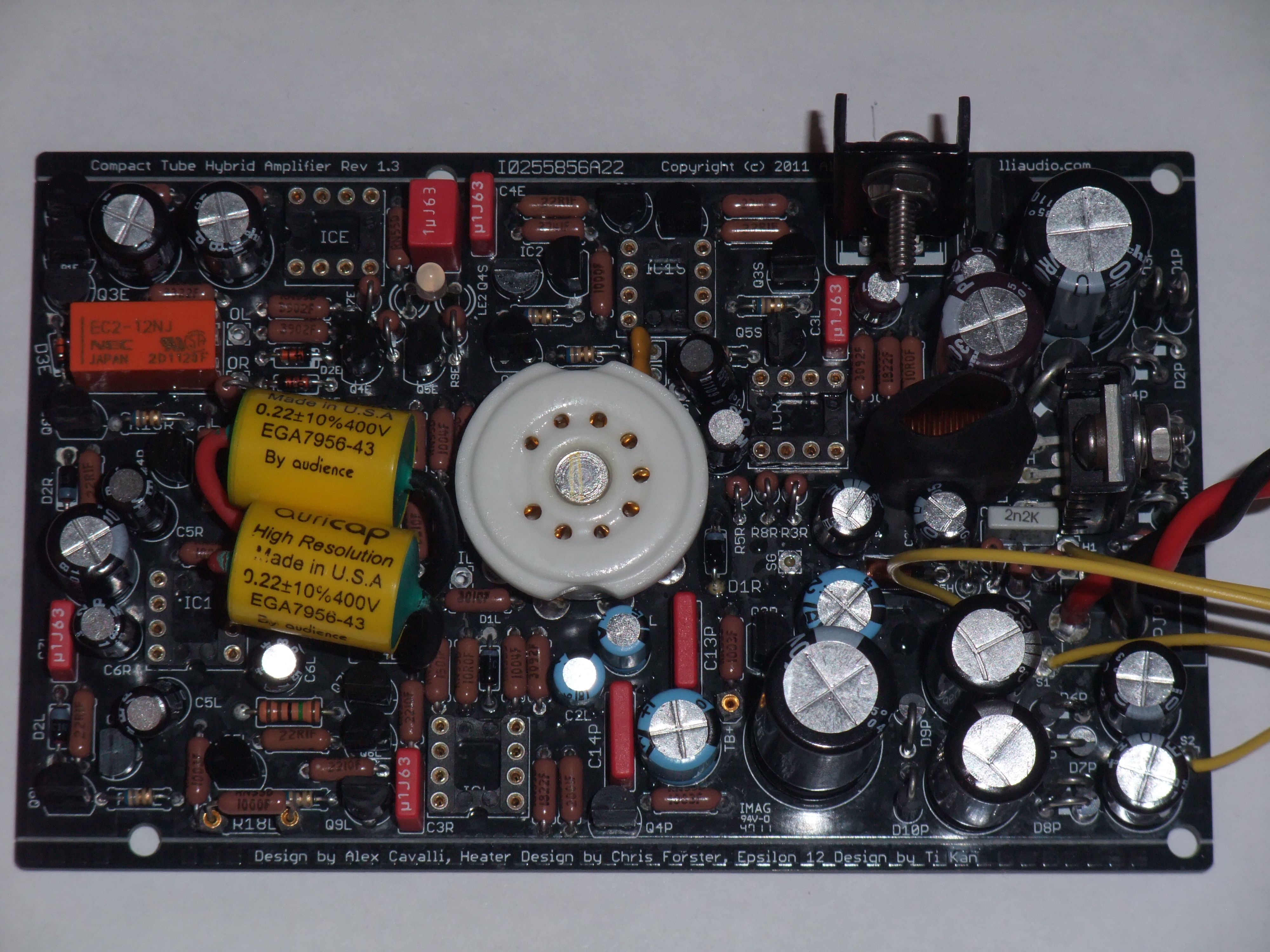
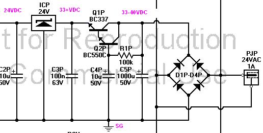
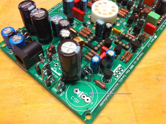
This is the one that still isn't in stock: MKS2-1.0/63/5
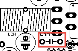
And this is what i was thinking to replace it with:
This is the one that still isn't in stock: MKS2-1.0/63/5
And this is what i was thinking to replace it with:


