


helzerr
New Head-Fier
- Joined
- Nov 8, 2007
- Posts
- 16
- Likes
- 11
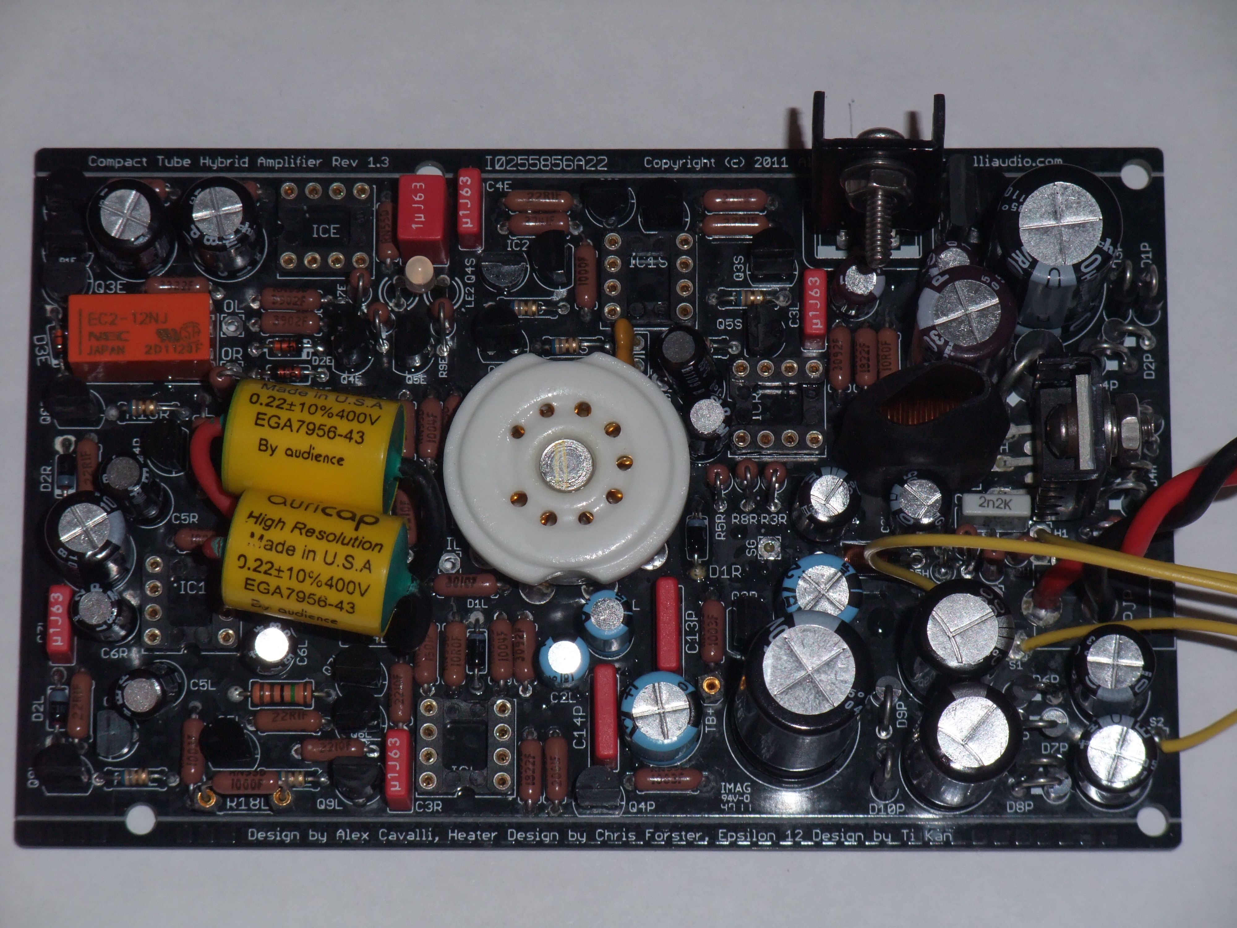
Is this CTH (equipped with 12BH7A) noise floor as measured by RMAA typical?
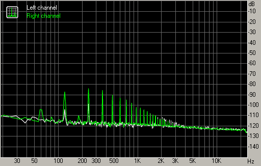
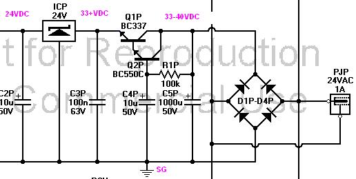
While I understand voltage doubler supplies like the one used for CTH's B+ may produce this sort of noise; with only ~2 mA load and capacitance multipliers I wouldn't expect this much 120 Hz and harmonics to be present at the output. Perhaps the heater supply is responsible? Thankfully, none of this noise seems to be audible through my 'phones.
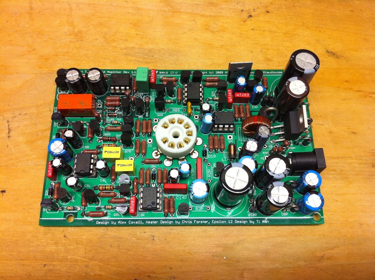
Note, this amp is built with R18=100Ω and the 330 μF C3H update installed.
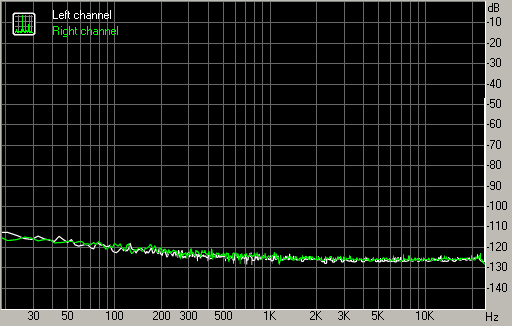
I tried another 12BH7A with nearly identical results. RMAA testing the DAC (y1) and another amplifier (Mini3) yield virtually no noise...
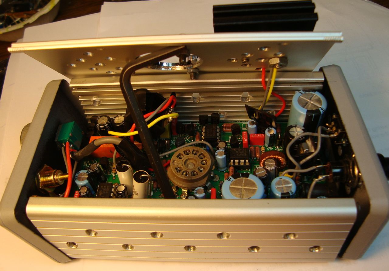
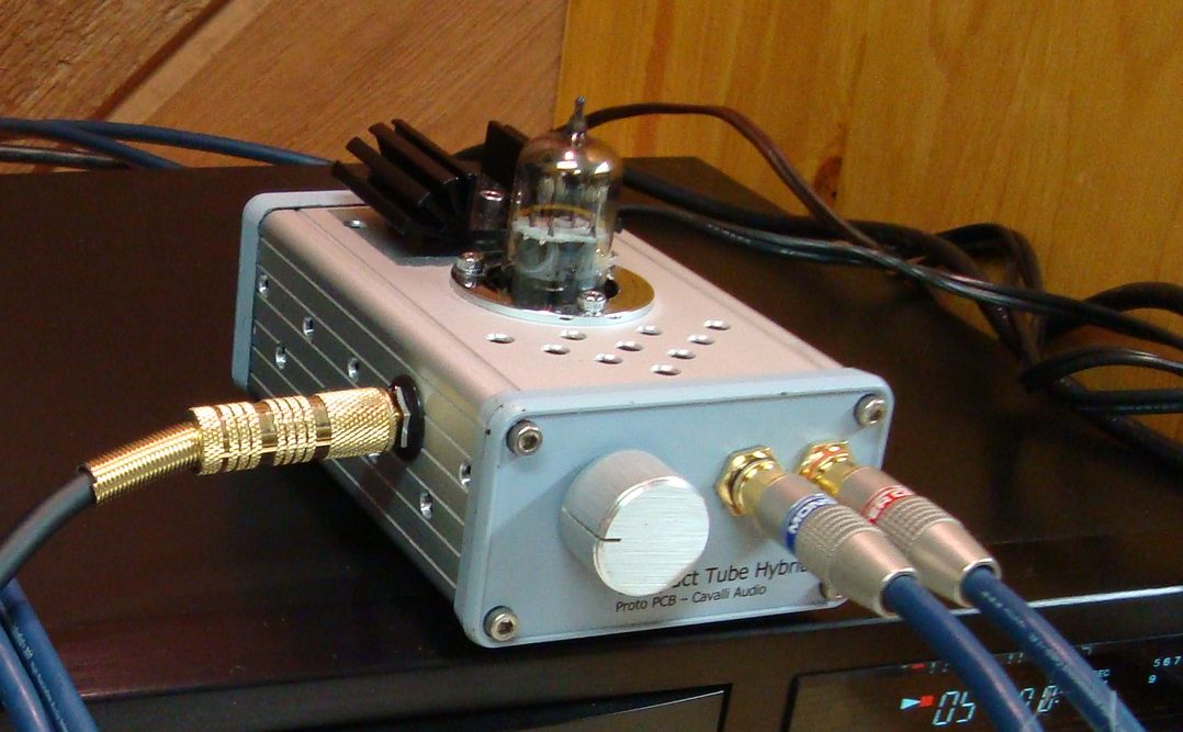
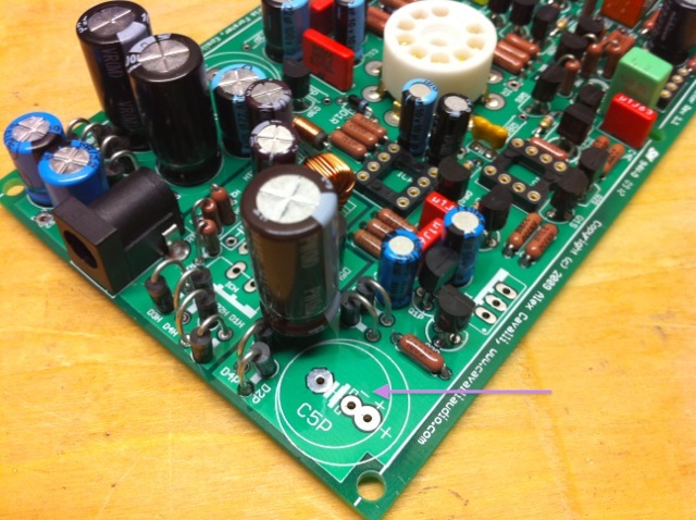
In my quest to build the quietest CTH on the block, the case is grounded to the SG point and all internal signal wiring is shielded, with each shield connected to its respective signal ground at only one end of the cable to prevent ground loops - I.E. input wiring shields are tied to IG at the volume potentiometer, output wiring shields tied to OG at the output jack, and power wiring is twisted-pair...
While I understand voltage doubler supplies like the one used for CTH's B+ may produce this sort of noise; with only ~2 mA load and capacitance multipliers I wouldn't expect this much 120 Hz and harmonics to be present at the output. Perhaps the heater supply is responsible? Thankfully, none of this noise seems to be audible through my 'phones.
Note, this amp is built with R18=100Ω and the 330 μF C3H update installed.
I tried another 12BH7A with nearly identical results. RMAA testing the DAC (y1) and another amplifier (Mini3) yield virtually no noise...
In my quest to build the quietest CTH on the block, the case is grounded to the SG point and all internal signal wiring is shielded, with each shield connected to its respective signal ground at only one end of the cable to prevent ground loops - I.E. input wiring shields are tied to IG at the volume potentiometer, output wiring shields tied to OG at the output jack, and power wiring is twisted-pair...


 olyester Film Capacitors 100V 0.22uF 5% Lead Free
 arlington Transistors NPN Transistor Darlington