The Wonderco heatsinks are the only ones I can recall seeing with a centre pin like that, but IMO you can use anything that'll physically fit on the board - there are a number of Aavid heatsinks that should work, for example. I don't really think mechanical rigidity is a major issue for this amp... and I'm trying to keep the DIY version as Australia-proof as possible, so I don't want to just come out and say, you know, "this is the
only part that will work here".
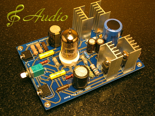
The resistors in the completed amp do look pretty high-power (I think they're probably 1W, not 2W - just a different manufacturer, hence different size from the 1W, R101), but I don't know if that's really necessary; old builds of Sijosae's MHHA used, I think, 1/4W resistors in most of the positions, which is what I plan to do. If you want to play it safe, Mouser carries audiophile-approved 2W resistors from Koa that are widely agreed to be identical to Kiwame, and they're not
obscenely expensive. There are other 1W and 2W film resistors (carbon or metal film; you almost certainly want to avoid wirewound ones) that will work just as well.
I for one don't see why R101
is 1W, anyway. Isn't it just an attenuator, between the signal in and ground? It's basically parallel to the volume pot, which is, what, 1/4W? Am I misinterpreting that?