β24: A discrete, cascoded, fully-differential power amplifier
Feb 3, 2010 at 11:53 PM Post #256 of 309
Got the boards mostly populated. Enclosure came yesterday. Got some aluminum scraps from the local metal works shop for the sub chassis assemblies. Will try to drill and tap the heat sinks this weekend. And finish populating the boards.

4328377285_048a8949ac.jpg

4329110924_a879697f63.jpg
 
Feb 5, 2010 at 9:31 PM Post #258 of 309
Few questions... mostly for Amb.

1. Looking at your build pictures, I can't figure out where C1-C8 go. I'm guessing they're tucked under the subchassis where the big electrolytics are? Or are they next to the rectifiers?

2. Where did you phyiscally put your star ground? Is it under the bottom plate?

3. Are the LED's supposed to be oriented so the long lead (+) goes to the side with the straight line?

I got my aluminum cutting table saw blade today (thinking about using aluminum diamond plate for either the sub chassis or the top of the enclosure) and have the heat sinks punched for drilling and tapping. Should have some more pictures this weekend for you mattcalf.
smily_headphones1.gif
 
Feb 5, 2010 at 9:42 PM Post #259 of 309
1. These are axial-leaded multi-layer ceramic caps, soldered directly across the big bridge rectifier terminals. You can see them in a couple of the pics.
2. I used a barrier strip, mounted to the bottom chassis plate. In the pics you see a bunch of black shrink-wrapped wires going to it.
3. An LED is a diode, so I use the convention of marked band = cathode ("-" pin). The LED's longer pin is usually the anode.
 
Feb 6, 2010 at 4:09 AM Post #260 of 309
Quote:

Originally Posted by oneplustwo /img/forum/go_quote.gif
Got the big trafo today! Here it is with my Senns to give you a sense of the size.


Blimey, that's as big as your head!
What size & weight is the finished amp going to be then?
 
Feb 6, 2010 at 4:38 AM Post #261 of 309
Quote:

Originally Posted by spookygonk /img/forum/go_quote.gif
Blimey, that's as big as your head!
What size & weight is the finished amp going to be then?


I think Amb said his was about 70 lbs IIRC? Mine will be pretty close. Same enclosure, almost identical build. His will be fancier though... no FPE for me. Just some DIY with my mini mill. I may add some wood accents though just for fun. And maybe use some diamond plate aluminum on the inside for a bit of an industrial accent. It will have little contasts here and there. Not sure if they'll really gel together but whatever. It'll be fun for me regardless.
biggrin.gif
 
Feb 6, 2010 at 6:04 AM Post #263 of 309
Is there a prize for heaviest B24? Or surely, there must be a technical benefit for having more mass... shielding, right?
biggrin.gif
There was some stainless in the scrap bin that I picked through for my pieces. And that stuff was HEAVY! Harder to machine though, and I don't really want to hurt myself lugging this thing around.

Drilled the holes in the heat sinks today and cut the pieces to size for the rear panel and the bottom sub chassis. (Aluminum cutting blade on the table saw rocks!) Did a little wet sanding too. Gonna try to tap the heat sink holes and figure out what I'm going to do for the top as well. Is diamond plate with slots in it too industrial looking?
 
Feb 6, 2010 at 6:14 AM Post #264 of 309
lol. While sheer mass might earn you bragging rights, you'll curse while working on the beast. I nearly smashed my fingers a few times when assembling mine.
 
Feb 14, 2010 at 9:51 AM Post #266 of 309
oneplustwo, did SumR not provide any documentation with your transformer?
Anyway, mine is a 50/60Hz dual primary, dual secondary unit.

Primaries:
a) 115V 17VA Blk*/Wht
b) 115V 17VA Brn*/Org

Secondaries:
a) 35V 15VA Red*/Yel
b) 35V 15VA Blu*/Gry

* denotes beginning of winding (polarity)

So, for 115V AC mains:
IEC live -> power switch -> Blk+Brn
IEC neutral -> Wht+Org
IEC ground -> chassis

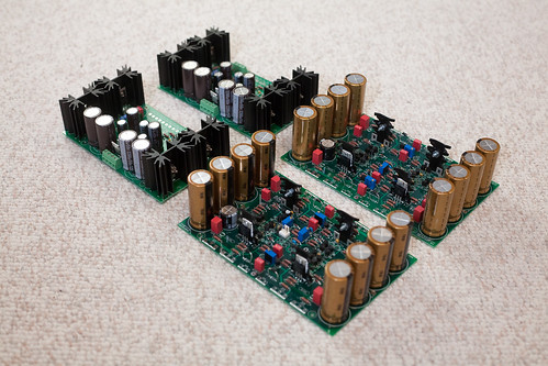
On the secondary side to the σ22s:
~ G G ~ = Red, Yel, Blu, Gry (either left to right or right to left)

Now, I don't know if this is indeed the very same transformer you have, or whether SumR always use the same wire color coding for custom-wound units, so don't just take my example at face value. Check the docs that came with your transformer to be sure. If no doc was supplied, you should contact SumR for clarification.
 
Feb 15, 2010 at 4:55 PM Post #267 of 309
I found the documentation... same exact color coding. Also, how did you take power from the IEC to both trafos? Did you use a terminal strip? And was the terminal strip after the power switch in your flow above?
 
Feb 18, 2010 at 7:12 AM Post #269 of 309
Amb - I'm considering orienting the big unregulated trafo vertically with it's axis going down the middle from to back. Any issues with that? I've seen it done on other B24's but wanted to see if there's any potential issue with trafo hum or anything like that. The smaller trafo for the sigmas would still be oriented as it is in your build.
 
Feb 18, 2010 at 8:17 AM Post #270 of 309
I don't know whether changing the orientation of the toroid would make a tangible difference in this case.

My main concern would be mechanical -- the toroid is secured by a single bolt, if it's sitting vertically then that bolt will be stressed by gravity. Also, the vertical "wall" to which you mount the transformer will also become load-bearing, so unless you use a very thick and stiff plate it would probably warp, and how that wall is attached to the rest of the case must also be very strong.
 

Users who are viewing this thread

Back
Top