β24: A discrete, cascoded, fully-differential power amplifier
Jan 17, 2010 at 9:34 PM Post #241 of 309
Quote:

Originally Posted by oneplustwo /img/forum/go_quote.gif
Amb - did you use thermal compound on both sides of the Al shim? (No insulator required for the Caddocks, right?)


The Caddock resistors are already isolated, so no need any more isolation pads. They should normally never get hot, so no thermal compound is necessary on them. For the MOSFETs I used Berquist Silpads -- no messy thermal compound either.

Quote:

Also, do you have a reco for what to use for internal wiring? I was thinking about stranded 16 gauge throughout but wasn't sure if that was beefy enough given some of the sections may carry significant current.


I used 18AWG for power and ground in the regulated sections, and 16AWG for the unregulated sections. All are "normal" stranded copper hookup wires.
 
Jan 18, 2010 at 1:42 AM Post #242 of 309
Amb - Any opinions about the signal wires to the boards and the output wires from the boards? I'm personally not interested in spending tons of money on fancy wire, but I would like to know what gauge (stranded) you'd recommend.

Also, any issue with routing the power wires from the rear panel IEC and fuse and then all the way to the front panel where the switch will be before heading back to the rear where I'm planning on putting a terminal strip? I figure I'd keep the routing in the center on the bottom under the subchassis to keep them as far away from the sigma and beta boards as possible.

Actually, any problems with using speaker cable wire for the regulated power? I have some 18 AWG stuff lying around that's nice and flexible... it's "oxygen free" copper.
smily_headphones1.gif
Might be able to find some 16 AWG stuff somewhere around the house too.
 
Jan 18, 2010 at 5:09 AM Post #243 of 309
I used Belden 8451 (foil shield with 2 internal conductors) cable to go from the rear panel input jacks and selector switch to the amp board. At the output I used 16AWG stranded hookup wires to the binding posts. The unregulated V+/V-/G and output wiring all have Molex .093 quick-disconnect inline connectors so the whole assembly can be removed for servicing without desoldering anything.

Yes, you can run the power wires to the front panel switch and back, as long as you keep them away from low level signal wiring and the amp boards.

As for using speaker cables, you could do that, but most "good" speaker cables have unnecessarily thick jackets for use inside the chassis.
 
Jan 18, 2010 at 5:39 AM Post #244 of 309
Ti,
what Bergquist Silpads are you using? i like to support my local guys whenever possible
smile.gif
.
 
Jan 18, 2010 at 5:41 AM Post #245 of 309
Quote:

Originally Posted by fishski13 /img/forum/go_quote.gif
Ti,
what Bergquist Silpads are you using? i like to support my local guys whenever possible
smile.gif
.


Digi-key BER120-ND
 
Jan 18, 2010 at 5:49 AM Post #246 of 309
Quote:

Originally Posted by amb /img/forum/go_quote.gif
Digi-key BER120-ND


perfect! Digikey is in my back-yard too. i have some mica i can cut down for TO-247, but i was also looking at the K series.
 
Jan 18, 2010 at 7:01 AM Post #247 of 309
Quote:

Originally Posted by amb /img/forum/go_quote.gif
I used Belden 8451 (foil shield with 2 internal conductors) cable to go from the rear panel input jacks and selector switch to the amp board.


What do you do with the shield wire? Just trim it flush or connect it to the chassis somewhere?

Do those molex connectors work just like the smaller ones? Looks like you have to buy the male and female housings but do you also have to buy male and female pins? Or do they housings come with them?

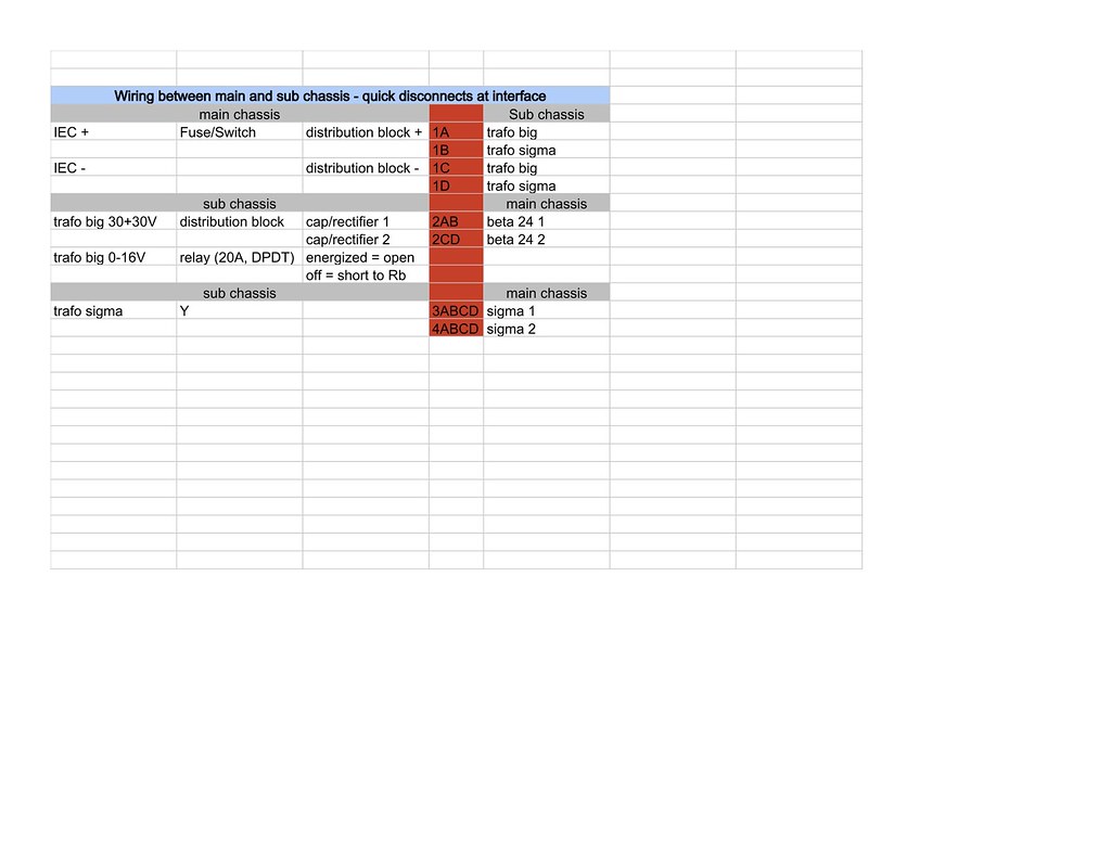
Here are the interfaces I was thinking I would want a quick disconnect (represented by red.)

4284415440_e9f4928b88_b.jpg


Looks like four molex connectors with 4 pins each... I think. Might have to split disconnect #2 of them into two 2-pin connectors. Need to think through it some more.
 
Jan 18, 2010 at 8:22 PM Post #248 of 309
Quote:

Originally Posted by oneplustwo /img/forum/go_quote.gif
What do you do with the shield wire? Just trim it flush or connect it to the chassis somewhere?


The shield wire carries the ground from the jacks to the board. See this diagram:

beta24_bal_unbal_sw_sch.png


Quote:

Do those molex connectors work just like the smaller ones? Looks like you have to buy the male and female housings but do you also have to buy male and female pins? Or do they housings come with them?


Yes, they are larger, heavier-duty versions of the Molex .062 series. You have to get the housings and pins for both sides. I picked up some from my local Fry's Electronics, sold as blister packs containing the housings and pins.
 
Jan 21, 2010 at 6:15 AM Post #250 of 309
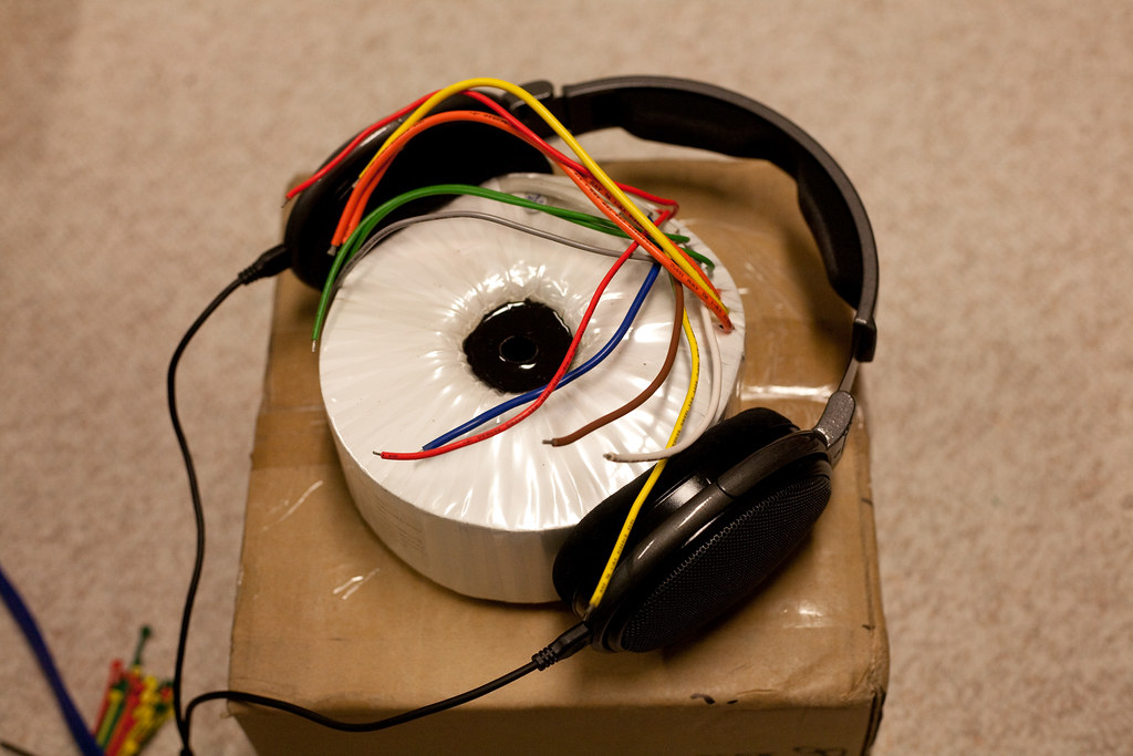
Got the big trafo today! Here it is with my Senns to give you a sense of the size.

4292503184_a6a186ee97_b.jpg


As I was looking at it, I started thinking about the wiring and had a couple things I wanted to verify.

1. I'm trying decide if I should use the 0-16V 0.5A or one leg of the 13-0-13V 1A secondary to feed the omron relay that will switch in the bleeder resistors. The nominal coil power is 1.7VA which either should handle fine. And the data sheet says it can take between 6 and 240 VAC so my thinking is that I should use the 13V... less is more. Does that make sense?

2. I believe the yellow wire (0 of the 30-0-30 secondaries) goes to the star ground. But does the YEL/GRN "SCN" wire also go to the star ground? Or should it be attached to some other part of the chassis? Does it matter? Here's the trafo wiring for reference:
600VA_large.jpg


3. For the primary, I think I just hook up the BRN and BLU wire to the IEC - and + respectively and just leave the WHI wire unattached. (I'm in the US.) Is that right?
 
Jan 21, 2010 at 9:27 AM Post #251 of 309
Quote:

Originally Posted by oneplustwo /img/forum/go_quote.gif
1. I'm trying decide if I should use the 0-16V 0.5A or one leg of the 13-0-13V 1A secondary to feed the omron relay that will switch in the bleeder resistors. The nominal coil power is 1.7VA which either should handle fine. And the data sheet says it can take between 6 and 240 VAC so my thinking is that I should use the 13V... less is more. Does that make sense?


That's a DC relay and needs 12V DC across its coil to operate. The transformer puts out AC, so you'll need to rectify/filter/regulate that to 12V DC. Something like a σ25 would be good here. I'd take one half of the 13-0-13 to do this.

Alternatively, you could look for an AC relay and skip the σ25. But it's may be hard to find an appropriate relay for this. I did a quick search of Mouser and Digikey and did not find any usable DPDT relay with 16V, 13V or 26V AC coils.

Quote:

2. I believe the yellow wire (0 of the 30-0-30 secondaries) goes to the star ground. But does the YEL/GRN "SCN" wire also go to the star ground?


Yes. The SCN lead is for the internal shield "screen".

Quote:

3. For the primary, I think I just hook up the BRN and BLU wire to the IEC - and + respectively and just leave the WHI wire unattached. (I'm in the US.) Is that right?


Leave the white wire unconnected (but insulated and tucked away). If you ever move to a country with 230V mains, then you need to change to use the white wire instead of the blue.
 
Jan 21, 2010 at 4:55 PM Post #253 of 309
Doh! For some reason I thought it was an AC relay. There seem to be lots of 12VAC relays out there. Would running 13VAC through it kill the relay? If yes, sigma25 may be in my future after all. Oh well... that's one of the few things in the Amb audio shop I haven't built yet. =)

I haven't weighed the trafo, but it's gotta be 12-15 lbs or so. I'll weigh it tonight...
EDIT: UPS says the entire box was 16.2 lbs. So it's probably right around 15 lbs.
 
Jan 27, 2010 at 1:58 AM Post #254 of 309
Does anyone have a good picture of the unregulated power supply from the leads of the trafo to the caps, to the rectifier, to the big caps? I'm trying to figure out in my head the best way to do this cleanly and safely.
 
Jan 27, 2010 at 7:12 AM Post #255 of 309
Just follow the schematic diagram as closely as possible, using thick, short wires, and you'll be fine:

Basically:
trafo -> rectifier -> bulk caps -> amp board
 

Users who are viewing this thread

Back
Top