


Sonic Wonder
Member of the Trade: Goldpoint Level Controls
- Joined
- Dec 6, 2010
- Posts
- 44
- Likes
- 12
RESULTS:
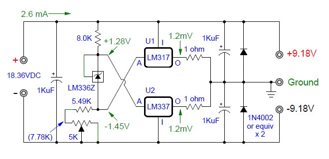
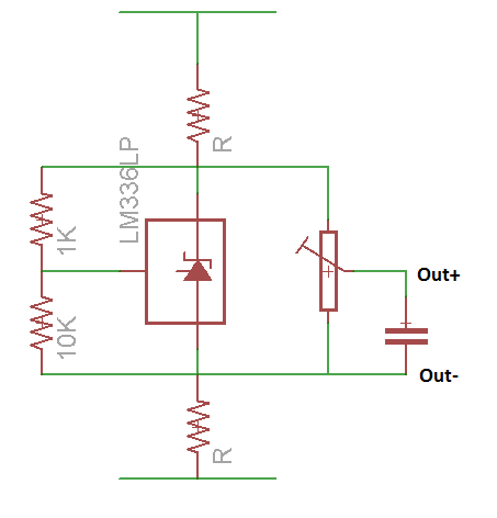
I got lazy and simplified the circuit again (practical considerations).
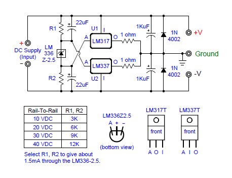
The Voltage reference is an LM336Z. (KT88's suggestion)
You can see results here similar to those obtained earlier using 4ea 1N4148 diodes in series to create a 2.69V voltage drop. The main difference is that the voltage divider is programmed for just about 1mA of current with the 8K resistors.
a) With no adjustment trimpot:
b) With a trimpot to center the virtual ground closely:
I suspect that the different voltages measured at the adjust pins of the regulators are coming from tolerance differences amongst the positive & negative regulators themselves, so using different ones should yield different voltage measurements at the adjust pins.
(a) above is the quick and dirty solution.
(b) above is if you need/want a closely centered virtual ground point. [Reduce the value of the associated resistor connected to the trimpot so that it, added to the midpoint value of the trimpot, is equal to the resistance of the fixed resistor at the other end of the voltage divider stack, of course.]
Either way, this circuit should make a good battery powered virtual ground, drawing only a few milliamps (2 or 3mA) of quiescent current - while also able to handle 50mA (without heatsinks) - or up to 1.5A per rail with heatsinking the two TO-220 devices.
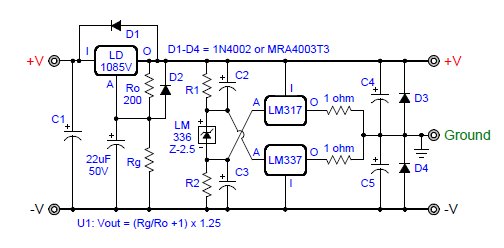
This note is being added a few weeks after posting the above: Further experiments with the two "self-adjusting" virtual ground circuits above show various instabilities. Therefore, use instead the circuits shown in the first article of this thread (on page one of this thread). If anyone works out a good way to use three terminal fixed or adjustable voltage regulators to make a "self-adjusting" "rail-splitter virtual ground, I would like to know about it. Thanks!
UPDATE to the comment above. The self-adjusting circuit now included in the first writing of this whole thread on page 1 works just fine! I love it! I had a wiring error in my prototype where I had connected the Adjust pin of the LM336 to its + pin. After removing THAT error, all is well. (So see first page - updated 15 April, 2013 - it's now showing the corrected circuit.) Also shown here:

I got lazy and simplified the circuit again (practical considerations).
The Voltage reference is an LM336Z. (KT88's suggestion)
You can see results here similar to those obtained earlier using 4ea 1N4148 diodes in series to create a 2.69V voltage drop. The main difference is that the voltage divider is programmed for just about 1mA of current with the 8K resistors.
a) With no adjustment trimpot:
b) With a trimpot to center the virtual ground closely:
Wondering if we would get better results with more current in the voltage divider, I upped it to about 4mA of current with 2.21K resistors. All that did was to use up more current, increasing the voltage drop across the output resistors slightly.I suspect that the different voltages measured at the adjust pins of the regulators are coming from tolerance differences amongst the positive & negative regulators themselves, so using different ones should yield different voltage measurements at the adjust pins.
(a) above is the quick and dirty solution.
(b) above is if you need/want a closely centered virtual ground point. [Reduce the value of the associated resistor connected to the trimpot so that it, added to the midpoint value of the trimpot, is equal to the resistance of the fixed resistor at the other end of the voltage divider stack, of course.]
Either way, this circuit should make a good battery powered virtual ground, drawing only a few milliamps (2 or 3mA) of quiescent current - while also able to handle 50mA (without heatsinks) - or up to 1.5A per rail with heatsinking the two TO-220 devices.
This note is being added a few weeks after posting the above: Further experiments with the two "self-adjusting" virtual ground circuits above show various instabilities. Therefore, use instead the circuits shown in the first article of this thread (on page one of this thread). If anyone works out a good way to use three terminal fixed or adjustable voltage regulators to make a "self-adjusting" "rail-splitter virtual ground, I would like to know about it. Thanks!
UPDATE to the comment above. The self-adjusting circuit now included in the first writing of this whole thread on page 1 works just fine! I love it! I had a wiring error in my prototype where I had connected the Adjust pin of the LM336 to its + pin. After removing THAT error, all is well. (So see first page - updated 15 April, 2013 - it's now showing the corrected circuit.) Also shown here:

