


gwitzel
100+ Head-Fier
- Joined
- Mar 26, 2015
- Posts
- 112
- Likes
- 104
I would like to use some of the holiday to write down impressions of the Clone Note LDR attenuator designed by Uriah Dailey.
Links:
http://www.buildanamp.com/Clone-Note-aka-Lighter-Note-rev-4-CloneNoteKit.htm
http://robmid42.wixsite.com/diyaudiokits/clone-note-preamplifier
The idea to order and build this attenuator kit is a result of experimenting with my other DIY project, a Bottlehead Crack headphone amplifier. After building the Crack I was very satisfied how my chain (Schiit Gungnir MB + Crack Speedball + HD600/650) sounded. However, I was curious what all the ‘upgrades’ for the Crack would do that are discussed here on head-fi and on the Bottlehead support forum. I don’t want to go too deep into a discussion of the Crack here, but I can clearly say that in my opinion one should be careful with many of the recommended changes. Many things I tried significantly degraded the SQ for my ears. The crack is really good in the stock Speedball version, first and foremost due to its good design. Changing parts, even if more expensive than the stock parts, might not result in the improvement you hope for (including changing to one of those super expensive Tung Sol 5998 power tubes which make a difference, but probably not one worth the $200 they ask for now).
Having said this, I felt that changing to a Valab 23 step attenuator ordered on eBay made an impact. The sound became more spacious and a bit more transparent. However, this is a pretty cheap attenuator, and I had some trouble with it: It makes noises while switching between levels, the steps are not fine enough for precise level control (even with resistor padding as described in Crack FAQ no.3), and with some tubes (6SN7 + adapter) the amp had significant hum which, as some forum members on the Bottlehead forum suggested, originated from an interplay with the attenuator. So I thought it is time to try something else.
I cannot remember how I found the webpage above. Unfortunately, there is not much information or impressions available on the web for this attenuator. The concept of LDR attenuators was intriguing to me (I don’t want to go into if and why it is a good idea to use LDRs for audio; this might end in a heated debate. Let’s just go with the assumption that it is NOT an outrageous atrocity). The information presented on the webpage looked interesting: It was supposed to be robust, easy to understand, no LDR matching necessary, adjustable impedance, precise channel matching, easy to modify for balanced operation.
I ordered, and Uriah delivered very quickly. He also sent building instructions, and a document with a detail description and explanation of the circuitry. He also offered and provided help via email or phone along the way. The kit includes 3 boards (switching board with voltage regulator and 24 position switch, and two channel boards with the LDRs and shunt resistor array), resistors, capacitors, multi-turn pots etc. Everything you need to build a single ended attenuator.
The principle of the attenuator is simple: it is a voltage divider that archives attenuation of the signal with a combination of resistors in series and parallel to ground (shunt). The shunt resistors are an array of metal film resistors, and the attenuator has one LDR in series for each channel. Since the resistance of the LDR is kept constant during operation, the input and output impedance of this kind of voltage divider changes with the volume level. Thus, it is important that the source has a small enough output impedance and the load a big enough input impedance for the attenuator to work well. The range of impedances of the attenuator can be adjusted and exact channel matching achieved via pots on the channel boards.
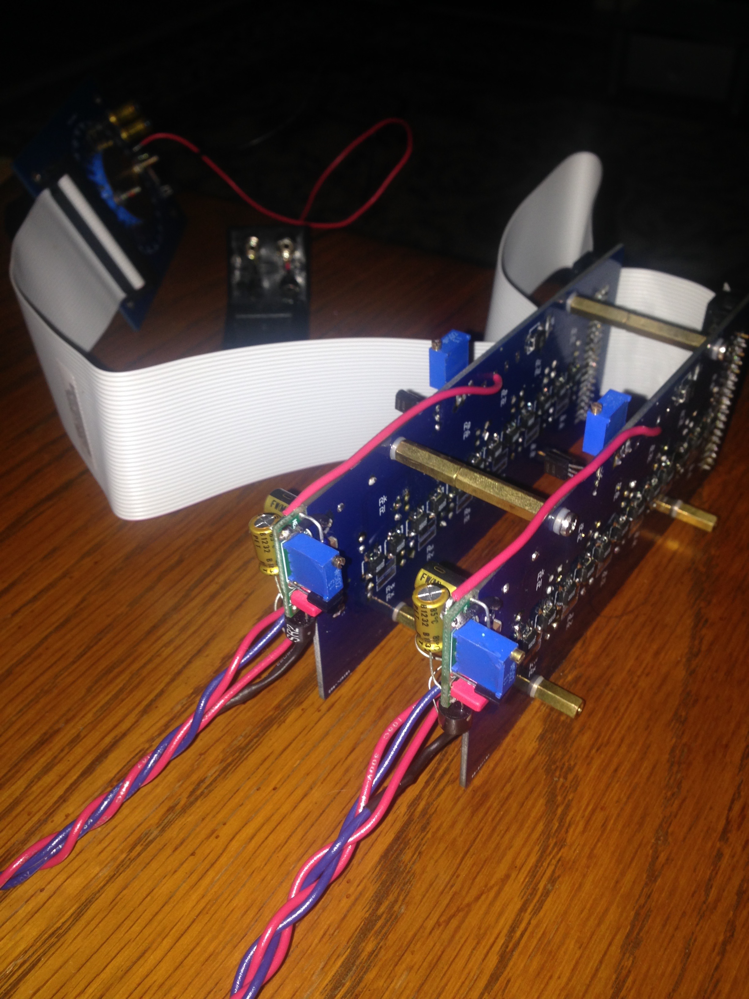
The realization of this simple principle is spectacularly well done. The boards are very high quality, so are the resistors. The signal never runs through the switch. The shunt array is controlled by optomos (semiconductor relays) that are themselves controlled by the 24 step switch. There is additional protective circuitry to make sure that during a failure of the power supply or the switch the signal is muted. The switch itself is on a separate board and connected via a ribbon cable in order to keep the signal paths to the channel boards short and at the same time provide the freedom to position the volume knob at the most convenient place. For balanced operation you can purchase two additional smaller (actually tiny) boards and parts to replace ground with a second LDR circuitry. I found a nice way to mount them to the main channel boards in a very organic way (see pictures below), but Uriah told me that he wants to look into including this option in the channel boards directly.
The building process was easy, but took quite a while. In my version the switch and all small surface parts where already soldered into place. To put all resistors in their right place was a tedious process that required a lot of repeated measurements of resistances. However, it gave me a lot of pleasure to do this thoroughly, and I had two working channel boards on first attempt. For tests, one can run this attenuator (or passive preamp) from a simple 9V battery. However, they don’t last much longer than a day or so. For permanent operation Uriah recommends a 12VDC power supply or a 12v 7AH battery.
And how does it sound?
I tried both versions, single ended and balanced, with my speaker system. I attached a 9V battery and adjusted the LDRs to 6k Ohm (this takes a while, the LDRs drift for a while). I put the Clone Note between my Gungnir MB DAC and my Parasound A23 power amp driving 4 Ohm Brocksieper Minara speakers (replacing my Parasound P5 preamp). The result is remarkable: The music flows much better, I can listen to the music at louder levels without it sounding pressed or overwhelming. The bass is more solid, while the treble remains very resolved but smooth. It is a significant improvement over my P5 preamp. Channel matching is very good. Both single ended and balanced work equally well, operation is dead quite. I will certainly use the Clone Note not only for my headphone setup, but for my speaker system as well.
I would like to mention that even if you are not inclined to try LDRs this set might be interesting for you. The LDRs can easily be replace by fixed resistors. The advantages of a reliable, good quality board with semiconductor relays will remain.
Since the Clone Note is way too large to be integrated into my Crack I decided to make a switch for my Crack that allows me to bridge its standard pot and build a full passive preamp with the Clone Note, a power supply, and a balanced to single ended receiver. My first preliminary pictures are below. I will keep updating this thread with my progress and provide more impressions later.
This is a fabulous DIY project which is very rewarding, both in building experience and in sound quality. I only can recommend to give it a try!
Happy Holidays!


Links:
http://www.buildanamp.com/Clone-Note-aka-Lighter-Note-rev-4-CloneNoteKit.htm
http://robmid42.wixsite.com/diyaudiokits/clone-note-preamplifier
The idea to order and build this attenuator kit is a result of experimenting with my other DIY project, a Bottlehead Crack headphone amplifier. After building the Crack I was very satisfied how my chain (Schiit Gungnir MB + Crack Speedball + HD600/650) sounded. However, I was curious what all the ‘upgrades’ for the Crack would do that are discussed here on head-fi and on the Bottlehead support forum. I don’t want to go too deep into a discussion of the Crack here, but I can clearly say that in my opinion one should be careful with many of the recommended changes. Many things I tried significantly degraded the SQ for my ears. The crack is really good in the stock Speedball version, first and foremost due to its good design. Changing parts, even if more expensive than the stock parts, might not result in the improvement you hope for (including changing to one of those super expensive Tung Sol 5998 power tubes which make a difference, but probably not one worth the $200 they ask for now).
Having said this, I felt that changing to a Valab 23 step attenuator ordered on eBay made an impact. The sound became more spacious and a bit more transparent. However, this is a pretty cheap attenuator, and I had some trouble with it: It makes noises while switching between levels, the steps are not fine enough for precise level control (even with resistor padding as described in Crack FAQ no.3), and with some tubes (6SN7 + adapter) the amp had significant hum which, as some forum members on the Bottlehead forum suggested, originated from an interplay with the attenuator. So I thought it is time to try something else.
I cannot remember how I found the webpage above. Unfortunately, there is not much information or impressions available on the web for this attenuator. The concept of LDR attenuators was intriguing to me (I don’t want to go into if and why it is a good idea to use LDRs for audio; this might end in a heated debate. Let’s just go with the assumption that it is NOT an outrageous atrocity). The information presented on the webpage looked interesting: It was supposed to be robust, easy to understand, no LDR matching necessary, adjustable impedance, precise channel matching, easy to modify for balanced operation.
I ordered, and Uriah delivered very quickly. He also sent building instructions, and a document with a detail description and explanation of the circuitry. He also offered and provided help via email or phone along the way. The kit includes 3 boards (switching board with voltage regulator and 24 position switch, and two channel boards with the LDRs and shunt resistor array), resistors, capacitors, multi-turn pots etc. Everything you need to build a single ended attenuator.
The principle of the attenuator is simple: it is a voltage divider that archives attenuation of the signal with a combination of resistors in series and parallel to ground (shunt). The shunt resistors are an array of metal film resistors, and the attenuator has one LDR in series for each channel. Since the resistance of the LDR is kept constant during operation, the input and output impedance of this kind of voltage divider changes with the volume level. Thus, it is important that the source has a small enough output impedance and the load a big enough input impedance for the attenuator to work well. The range of impedances of the attenuator can be adjusted and exact channel matching achieved via pots on the channel boards.
The realization of this simple principle is spectacularly well done. The boards are very high quality, so are the resistors. The signal never runs through the switch. The shunt array is controlled by optomos (semiconductor relays) that are themselves controlled by the 24 step switch. There is additional protective circuitry to make sure that during a failure of the power supply or the switch the signal is muted. The switch itself is on a separate board and connected via a ribbon cable in order to keep the signal paths to the channel boards short and at the same time provide the freedom to position the volume knob at the most convenient place. For balanced operation you can purchase two additional smaller (actually tiny) boards and parts to replace ground with a second LDR circuitry. I found a nice way to mount them to the main channel boards in a very organic way (see pictures below), but Uriah told me that he wants to look into including this option in the channel boards directly.
The building process was easy, but took quite a while. In my version the switch and all small surface parts where already soldered into place. To put all resistors in their right place was a tedious process that required a lot of repeated measurements of resistances. However, it gave me a lot of pleasure to do this thoroughly, and I had two working channel boards on first attempt. For tests, one can run this attenuator (or passive preamp) from a simple 9V battery. However, they don’t last much longer than a day or so. For permanent operation Uriah recommends a 12VDC power supply or a 12v 7AH battery.
And how does it sound?
I tried both versions, single ended and balanced, with my speaker system. I attached a 9V battery and adjusted the LDRs to 6k Ohm (this takes a while, the LDRs drift for a while). I put the Clone Note between my Gungnir MB DAC and my Parasound A23 power amp driving 4 Ohm Brocksieper Minara speakers (replacing my Parasound P5 preamp). The result is remarkable: The music flows much better, I can listen to the music at louder levels without it sounding pressed or overwhelming. The bass is more solid, while the treble remains very resolved but smooth. It is a significant improvement over my P5 preamp. Channel matching is very good. Both single ended and balanced work equally well, operation is dead quite. I will certainly use the Clone Note not only for my headphone setup, but for my speaker system as well.
I would like to mention that even if you are not inclined to try LDRs this set might be interesting for you. The LDRs can easily be replace by fixed resistors. The advantages of a reliable, good quality board with semiconductor relays will remain.
Since the Clone Note is way too large to be integrated into my Crack I decided to make a switch for my Crack that allows me to bridge its standard pot and build a full passive preamp with the Clone Note, a power supply, and a balanced to single ended receiver. My first preliminary pictures are below. I will keep updating this thread with my progress and provide more impressions later.
This is a fabulous DIY project which is very rewarding, both in building experience and in sound quality. I only can recommend to give it a try!
Happy Holidays!

")
