Asus Essence One Headphone Amp/DAC (CeBIT 2011)
Oct 7, 2015 at 6:23 AM Post #3,196 of 3,573
Thanks RainfallSky!
 
Did you noticed that trebles are a bit accentuated on OPA2132? More details could be heard, comparing with NE5532, of course.
 
Could you please detail a little bit the LT1498, at least in compare with stock NE5532. Things like details, bass and soundstage should help a lot for all os us, I guess. Also, how hot LT1498 get, comparing with 5532?
 
Thaks again!
 
Oct 7, 2015 at 8:02 AM Post #3,197 of 3,573
Trebles accentuated too yes but it's like there are blank space between vocal and highs where more details should be but there are none.. I would say OPA2132 is exactly like equalizer when you toying with it. Some frequencies set too high and some to low that you barely hear sounds you know should be there or don't hear them at all. Sound is too artificial, too torn.
LT1498 hmmm. Sound stage is one of the strongest parts of LT1498. It's wide and detailed with good sence of presence. I think bass sound level is very good. LPF and Buffer add too of course but i don't want to add more nor do a want less. It cold go very low but not infra low.
biggrin.gif
 Vocal feels slightly closer to you. Highs are soft with no harshness. This all is how i hear it on my modded Essence One and my system. I changed all electrolytic capacitors on sound card PCB and a bit on power supply PCB, now it looks like this.

 
Oct 7, 2015 at 9:38 AM Post #3,199 of 3,573
LPF - OPA1611 (mono ver. of OPA1612)
RCA - OPA627SM
XLR - OPA627AU
 
627's are left from the times when i had Asus Essence ST. I don't really use XLR outputs. And 627SM was reckless expensive idea.. 
rolleyes.gif
 Stock LME49720 at headphone output. I think LME49720 is still the best there, thats my opinion. They still could be be upgraded to LME49720HA or dual LME49710HA. But LME49710HA only by using +2 DIP8 sockets like here:

 
Oct 23, 2015 at 5:07 PM Post #3,200 of 3,573
I was looking to LM2940 and LM2990 datasheets recently and realized that noise and ripple specs are not OK at all. These LDOs are just not for Hi-Fi use, if you ask me, they are mostly used in batteries equipped electronics (drones, small electric vehicles etc.) because they are TO220 and can be easily connected to a radiator, are 0.5V LDOs and can sustain continuous 1.5A. I honestly have no idea why ASUS picked those up in favor of less expensive and better 7812/7912 (at least on the paper); maybe someone from this forum could enlighten me, please.
 
Manufacturer's specs for 5V regulators
           LM2940/5 NJM7805  LT1963A
Ripple:   72dB 78dB       63dB
Noise : 150uV 45uV       40uV
Essence One needs around 0.8-0.9A for the 5V rail.
I estimate LT1963A's noise at around 55uVRMS@5V/1A load, based on datasheet.
NJM7805's noise is 45uV@5V/0.5A load, but no data @1A load, so perhaps LT1963A might be a better option for the +5V rail.
 
Manufacturer's specs for 12V regulators
          LM2940/12 NJM7812 LT1963A
Ripple:     66dB        71dB      63dB
Noise :   360uV        75uV 40uV
Essence One needs around 0.4-0.5A for the +12V rail.
I estimate LT1963A's noise at around 130uVRMS@12V/0.5A load, based on datasheet.
NJM7812 noise is 75uV@12V/0.5A load, based on datasheet, so perhaps for only 0.5A NJM7812 might be a better option for the +12v rail, though most people consider LT1963A better (me included, especialy for loads over 0.5A).
 
Manufacturer's specs for -12V regulators
          LM2990/12 NJM7912 LT3015/12
Ripple:    52dB        68dB 53dB
Noise :  500uV 150uV 60uV@-1.22V
Essence One needs around 0.4-0.5A for the +12V rail.
I estimate LT3015-12's noise at approx. 150uVRMS@-12V/0.5A load, based on datasheet (with additional CFF capacitor).
LM2940-12's noise was tested on the datasheet at only 5mA!
NJM7912 noise is 170uV@12V/0.5A load, based on datasheet, so perhaps LT3015-12 might be a better option for the -12V rail, though NJM7912 would be good enough as well.
 
I ordered already 1xNJM7812, 1xNJM7912, 1xNJM7805FA, 2xLT1963A and 1xLT3015, maybe I'll have some time (this year) to change LM2940/LM2990 LDOs with something better (lower noise, better ripple rejection). I'll probably double PSU input capacitors too.
 
Till now I just added 1xWIMA MP3 on mains, 3 x non-polarized capacitors on the 3 AC rails (for +/-12V and for +5V) and 3 x tantals 10uF/35V for each DC output rail.
 
BTW, what's the use of LM385 LM358 soldered on the back of PSU's PCB, please? Is this OPAMP acting as a protection by comparing +12V and -12V and if difference is not zero then it cancels +12 and -12V outputs for few milliseconds, until LDO's output will get stable? I believe if LM2940 would have let's say 0.1 seconds faster startup than LM2990, then some OPAMPs from I/V, LPF or BUFFER might have high DC output because of that, right? Please correct me if I'm wrong, thanks.
 
L.E.: What's important is not to combine complementary regulators: NJM7812 with NJM7912 and LT1963A with LT3015 and not to mix them!
 
Oct 24, 2015 at 2:39 AM Post #3,201 of 3,573
Just realized that there is a ground-loop issue on the motherboard of E1, right where the power plug is connected to. There are 3 pins for ground and 3 black cables (3 grounds for +/-12V and +5V) and the top-right pin is not connected to the other 2 pins from the middle, so...here's a ground-loop I'd say.
 
Here's the AC ripple+noise taken to the first DC-plug from the PSU:

 
Here's the noise taken from the 2'nd DC plug, from the motherboard:

You can easily see the 10mV p-2-p noise signal bumping up every 25uS on the -12V rail...I have no idea where this comes from, but after correcting that ground-loop by shorting the 2 ground pins from the plug going to motherboard with a small copper wire resolved the issue.


You can see the small copper wire between 2 ground-pins to correct this issue. Things look much better now.
 
I find it quite strange why ASUS didn't shorten the 3 ground pins on the motherboard and choose only to shorten just 2 of them. ?!?
 
Is there anyone here with a scope and time to measure AC ripple & noise, please? I have the MUSES motherboard, the one with gain jumpers, so I'm trying to see if this issues exists in non-MUSES motherboard too. I'm talking about the -12V voltage which is having this ground-loop that needs to be corrected manually (a simple short-circuit on the back of the PCB would be best, probably).
- first measurement on plug 1 (from PSU) with plug 2 not connected to motherboard;
- 2'nd measurement on plug 1 (from PSU) with plug 2 connected to motherboard;
- 3'rd measurement on the 2'nd plug from the motherboard with plug 2 not connected to motherboard;
- 4'th measurement on the 2'nd plug from the motherboard with plug 2 connected to motherboard.
 
Nov 5, 2015 at 9:51 AM Post #3,202 of 3,573
Hi again guys,

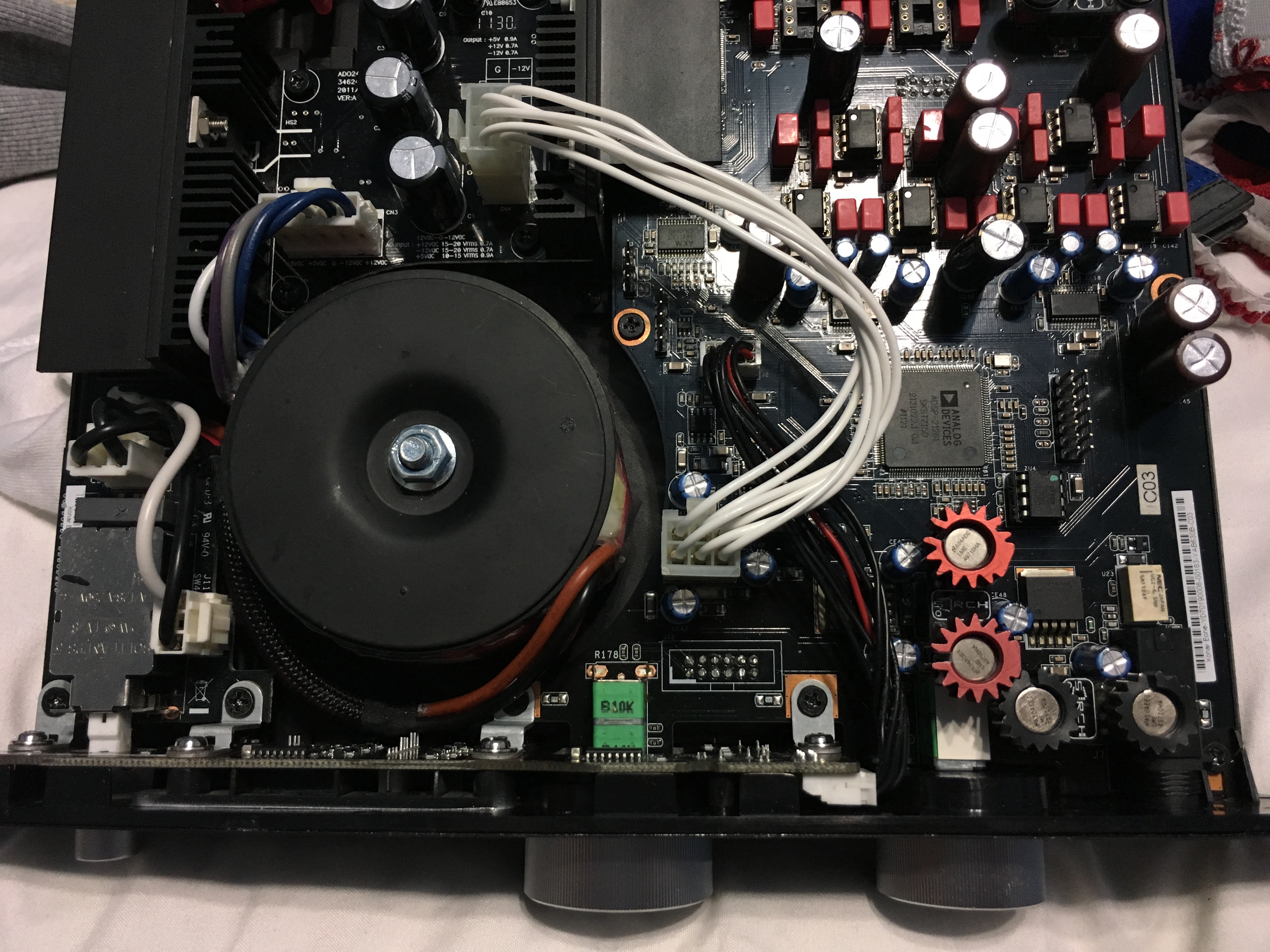
I was able to identify another PCB issue in our beloved Essence One DAC, just look at the following image:


This is how +5V looks like on a 20 Mhz scope bandwidth (didn't even bothered with 100 Mhz bandwidth because I don't really care about high MHz noise pollution): over 5mV peak-to-peak of ripple+noise The signal looks quite strange, is like ripple+noise but also looks like is oscillating a little bit...strange enough to give me a couple of hours of thinking. :)

So, I proceeded to replace voltage regulator for +5V with NJM7805 and here's the new measurement screenshot:


The image is much better, because now the voltage looks more like a ripple + noise, so...at least it looks like something more normal to me, but this ripple is totally not part of Hi-Fi domain. It probably looks worse than my old Pioneer 40W amplifier's PSU. :)

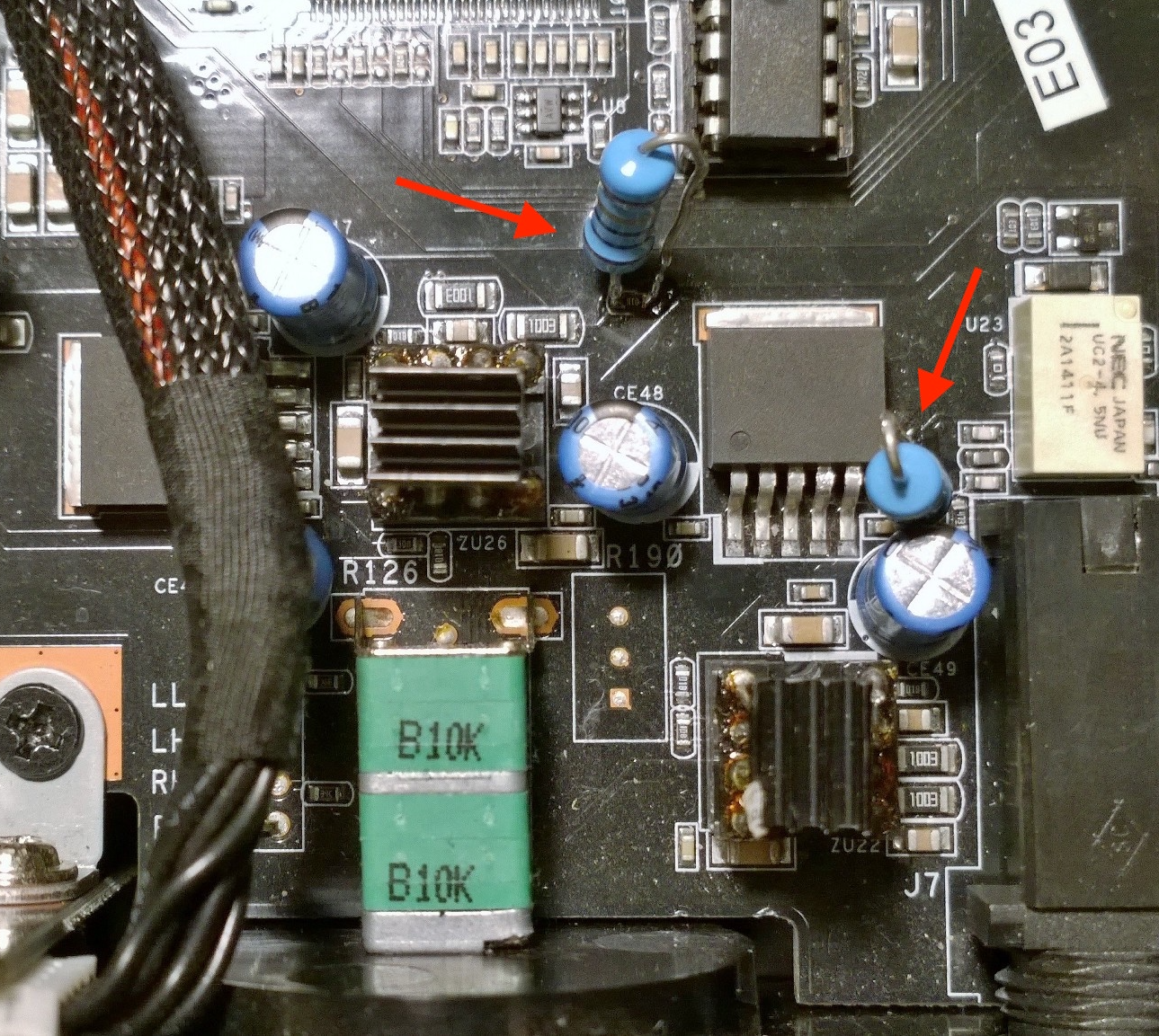
After few more hours of trying to understand what's wrong with this PSU, I realized that when I place the scope directly on regulator's pins scope's image looks way much better than when placing scope probes on power plug pins. Hmmm...initially I thought the +5V path was too thin, so I connected a direct cable between power regulator (NJM7805 output pin) and +5V power plug, but this didn't helped at all. Then, I did the same for Ground by routing a thick cable between power regulator GND directly to the 3 GND pins from the power plug and I realized that ripple settled down a lot now and signal looks much better. Then I quickly created a CRC filter to further decrease ripple, by adding a 1ohm resistor and 2200 uF cap (1800uF + 1ohm + 2200uF) just before NJM7805 input pin and here's how it looks like right now:


(Feel free to compare this image with the first one! 2mV p-p vs. 5mV p-p)

I will try replacing the 1 ohm resistor with another one having 5 ohms or more and if I'll be able to recrease the ripple even further I'll let everyone know.

I had also replaced +12/-12V regulators with NJM7812/7912, but didn't really noticed much improved, just a little bit of noise and ripple because NJMs are better regulators, but not so much to be completely thrilled. I added 3300uF caps for +12V/-12V as well (without any resistors, because lacking PCB space) and here are the 2 screenshots for +12V and for -12V:


+12V is not perfect, but at least is not so worse as it used to be the +5V initially. Anyway, +/-12V are only used for OPAMPs and these are having at least 80dB PSRR, so...I won't worry about +/-12V ripple so much. I mostly care about the +5V ripple on this DAC.


-12V looks quite OK I'd say.

If you do have a scope and some time to measure the AC ripple & noise when E1 is powered on and running (either directly on PSU's plug, either on the back of PSU's PCB), then please do. This way we can see if the same +5V ripple issue exists on other E1 DACs.

Note: All of the above measurements were done with E1 connected to PSU! Please note that when E1 is not connected to PSU's plug, the +5V, but also +12V and -12V, look almost perfect, without any ripple issue!
 
Last edited:
Nov 5, 2015 at 9:58 AM Post #3,203 of 3,573
Some pictures from my testbench, but please excuse the mess and lack of flux and time to clean up the PCB after my work.
 

First run. PCB GND trace thick wire that proves that GND from this PSU sucks a lot when on load.
 

2'nd run, with resistor moved from back of PCB. a lot of mess, I know...please don't kill me for this. I promise I'll rearrange these components...sometimes.
 

The 3 final capacitors were removed, because the ripple measured on the PCB route was rerouted to them (shortest path was not meet). Anyway, I had them replaced with smaller tantalums, because lack of space. Also, a 2'nd GND wire is in place now to decrease a little bit more AC ripple from +/-12V.
 
Thanks!
 
Nov 5, 2015 at 7:08 PM Post #3,204 of 3,573
More news about improving my E1's PSU:


BEFORE:AFTER:

+5V with poor GND PCB + LM29940-5 + 1800uF on input + 330uF on output​

+5V with GND resolved by soldering a couple of thick wires + NJM7805 + CRC filter (1800uF+3.3ohms+2200uF) + 2x10uF tantalums & 1x220uF SILMIC2​


+12V with poor GND PCB + LM2990 + 1200uF on input + 220uF on output​

+12V with GND resolved by soldering a thick wire + NJM7912 + 1200uF & 3300uF on input + 1x10uF tantalum & 2x100uF Nichicon KA on output​

The -12V was OK by default, so no need for pictures here, because after changing the LM2990 regulator with NJM7912 and installing an additional 3300uF capacitor didn't made a big difference. It was an improvement, but nothing to applause here.

Resolving motherboard PCB ground-loop for -12V GND (explained a couple of posts above):


Installing EMI/RFI filter + additional WIMA MP3 cap + ground-loop filter (resistors+capacitor between E1 ground and power lines ground, as seen on Meier-Corda headamps and DACs):


Resolving poor PCB ground plane:
- 1 x thick copper red wire going to +5V regulator GND (better view on my previous post)
- 1 x thick copper red wire going to GND from the 2 caps for +/-12V (better view on my previous post)
- 1 x (not so thick) aluminum wire for +12V regulator GND


Like I said in my previous post, if there's anyone with a decent scope, please take some measurements carefully, so we can compare results and see if the above PSU mods can be applied to other E1s.

Thanks!

L.E.: In case you want to install an EMI/RFI filter inside the E1's case, please, for your safety, use an encapsulated and electrically isolated EMI/RFI filter. The one I've used in one from the above pictures was not isolated, but I had it replaced after I finished my tests. Do not use non-isolated EMI/RFI filter inside the metallic case of the Essence One or other electrical appliances!
 
Last edited:
Nov 8, 2015 at 2:44 AM Post #3,205 of 3,573
Looks like the inefficient AC ripple filtering from E1's power supply was also noticed here http://personalaudio.ru/detail/na_chto_vliyaet_kachestvennoe_pitanie_v_tsifrakh/ and here http://tweak.just-click.ru/?p=13 as well. The guy from the last link realized that E1's PSU is most likely oscillating and decided to remove the internal PSU with another one (DIY) and now he looks happy enough.
 
From http://audiohobby.ru/dorabotka-asus-xonar-one.html (thanks again to Google translate) looks like the dual PCM1795 DAC is using all the 4 DAC outputs only when balanced external amplifier is used (another good reason to use an external balanced amplifier and balanced headphones). When using internal amplifier (LM49720+LME49600) or unblanced RCA outputs E1 takes the output signals only from I/V OPAMPs no. I and no. III; the OPAMPs II and IV remain unused (I believe only half of LPF OPAMPs are actually used). I wonder if other manufacturers are doing the same. For example, M2Tech Vaughan is using 8xPCM1795, so...perhaps Vaughan is using 8xPCM1795 in dual-mono config and 4-chips are used for unbalanced and all the 8-chips are used for balanced...I don't know.
 
Nov 8, 2015 at 5:58 PM Post #3,206 of 3,573
I really care about the +5V rail, because this is powering the analog circuits from inside PCM1795 DACs and also +5V provides power for the step-down regulator to 3.3V that powers the digital part from both PCM1795. So, I moved on by replacing again the +5V regulator with the LT1963A - 40uV RMS noise (7K & 2.2K resistors divider); didn't really noticed a big improvement in ripple, but noise settled down a little bit.


Anyway, I just added a 4700uF capacitor directly on LT1963A output pins and ripple+noise decreased to almost 500uV p-p. I believe this is quite a decent value after all (compare +5V ripple+noise from the below picture with +5V from a couple of posts above).


As for the step down regulator from 5V to 3.3V, that's a RICHTEK 9025; it's not featured as being low noise and it's not recommended for use in DAC applications by the manufacturer, but to be honest the noise for +3.3V is quite low (about 350uV p-p), so I'm not worried about the noise here.


Nov 10, 2015 at 7:02 PM Post #3,207 of 3,573
  Looks like the inefficient AC ripple filtering from E1's power supply was also noticed here http://personalaudio.ru/detail/na_chto_vliyaet_kachestvennoe_pitanie_v_tsifrakh/ and here http://tweak.just-click.ru/?p=13 as well. The guy from the last link realized that E1's PSU is most likely oscillating and decided to remove the internal PSU with another one (DIY) and now he looks happy enough.
 
From http://audiohobby.ru/dorabotka-asus-xonar-one.html (thanks again to Google translate) looks like the dual PCM1795 DAC is using all the 4 DAC outputs only when balanced external amplifier is used (another good reason to use an external balanced amplifier and balanced headphones). When using internal amplifier (LM49720+LME49600) or unblanced RCA outputs E1 takes the output signals only from I/V OPAMPs no. I and no. III; the OPAMPs II and IV remain unused (I believe only half of LPF OPAMPs are actually used). I wonder if other manufacturers are doing the same. For example, M2Tech Vaughan is using 8xPCM1795, so...perhaps Vaughan is using 8xPCM1795 in dual-mono config and 4-chips are used for unbalanced and all the 8-chips are used for balanced...I don't know.

 
Hi Raoul,
 
Does he give out the schematic for the DIY PSU?
 
Nov 11, 2015 at 12:27 AM Post #3,208 of 3,573
Hello,
 
Not really, but after analyzing the PCB I got the conclusion that it should be the same schematic like old LM78xx/79xx, just ASUS choose LM2940 and LM2990 regulators instead. The schematic should be quite similar with the one from TI's 2940/2990 datasheets.
 
ASUS added a LM358 OPAMP between those 2 power regulators that probably drives them to trigger the 2 voltage rails (+12V and -12V) at the same time, to prevent any possible DC output on I/V, LPF and output buffers, but to be honest I haven't spent much time to analyze this; it was a no-brainer for me that replacing the regulators with something equivalent but with better specs should improve PSU's parameters (initially I wasn't aware that there's a PCB/traces issue). Jimmy did some great shots to this PSU: http://jimmyauw.com/2013/03/23/asus-xonar-essence-one-power-supply-removing-the-capacitors/, so feel free to check his blog as well for any possible details. In case I'm wrong about the usage of the LM358 in this PSU, please let me know...thank you!
 
I can't really recommend you to start doing some work on this PSU unless you have access to a decent scope (1mv/div. should be fine). On my 2204A PicoScope (10mv/div, 100mv/scale) I was able too see that voltage signals look a bit nasty, but I wasn't able to see how really signals look like until I borrowed a digital Tektronix (1mv/div, 8mv/scale) from an old friend.
 
Cheers!
 
P.S.: I just removed the I/V OPAMPs from positions 2 & 4 and indeed this only affects the balanced outputs only. So, you only need 2 x I/V OPAMPs connected in positions 1 and 3 to have audio on headamp and on RCA output. That might save some money to people wanting to roll new OPAMPs.
 
Nov 11, 2015 at 4:26 AM Post #3,209 of 3,573
Just realized now that Mach3 was asking about the DIY PSU schematic and not about ASUS schematic...sorry for my "missing morning coffee" reply, but my initial answer was related to ASUS PSU. :frowning2:
 
No schematic for the DIY PSU, sorry, but if you look closely at his work you'll see that he's using LM317/337 and the schematic looks similar with the one from the LM317/LM337 datasheet. Honestly, I can't recommend using these old regulators when we all know that LM or NJM 7812/7912 or newer LT1963A/LT3015 are much better in handling noise than 317/337. Looks like this guy is using a nice CRC filter in front of the power regulators, just zoom into his PSU a little bit and you'll see big caps and 3-5Watts resistors (perhaps paralleled).
 
If yo don't want to DIY, I believe you can also use eBay to search for some good PSUs: for the +/-12V NJM7812/NJM7912 or LT1963A/LT3015, but for the +5V you might want to try the TPS7A47 4.17uV/1A power regulator or at least LT1963A 40uV/1.5A (with 7K & 2.2K resistors divider in case you want to DIY).
 
Of course, if someone will really want to make this DAC noise-free, then Per Anders might be the right person for this. :) Also, DIYTHINK and another 2 guys are selling quite good power regulators on eBay (one guy is from Ljubliana and another one from Emirates). I'm thinking of buying one PSU with TPS7A47 for the +5V rail and to buy or to DIY a dual PSU with LT1963A/LM3015 for the +12V and -12V rails, just...not sure how to stick/glue all these regulators on the existing nice black radiator...will see about it anyway.
 
Regards, 
Raul.
 
Nov 11, 2015 at 9:24 AM Post #3,210 of 3,573
P.S.: I just removed the I/V OPAMPs from positions 2 & 4 and indeed this only affects the balanced outputs only. So, you only need 2 x I/V OPAMPs connected in positions 1 and 3 to have audio on headamp and on RCA output. That might save some money to people wanting to roll new OPAMPs.

 
We was just talking about it some time ago on erm.. another forum. If you look at the sound card board, almost all elements on the board are marked. (Thats nothing new, i type it for other readers) So, I/V OpAmp sockets ZU12 and ZU17 are for unbalanced outputs (RCA/Headphones) and party for balanced. ZU16, ZU19 sockets are for balanced (XLR) outputs. We are in the middle of experiments (for unbalanced line only ofc.) removing ZU16, ZU19 OpAmps and put 0.01uf film capacitor betwin 4-8 legs and same for ZU23, ZU24 (XLR outputs). Easy shunt whitout solder. Capacitance value are part of experiments too. Sound clarity improvements are very interesting. You can experiment further puting electrolytic capacitors betwin 3-4 and 5-8 legs for I/V. (Do not use same method for XLR output).
 

Users who are viewing this thread

Back
Top