No prob Sahib, I think you are confusing Cascode with triode. Secondly, you are missing the input tube stage from the schematic...so alot more going on to discuss...
BTW, whats the problem with cascode. Its hard to create a stable current for driver stage transistors. An input from a source has plenty of current but cannot correctly drive output transistors due to its distance from the driver stage. This creates a delay and increased resistance for the driver input stage.
Especially if using bipolar transistors, their lower input impedance will create RLC high and low pass filters. Also to get the correct gain factor, some kind of voltage drop has to occur. The typical gain or beta factor for a transistor can be between 25 and 80. NPN and PNP from a bipolar series often do not have the same gain. Thus the need to create a dc offset to the drive stage signal.
This could be accomplished using a resistor divider and a diode gate to sum in a bias voltage. The problem would still be the slew rate of the source before and after this voltage division.
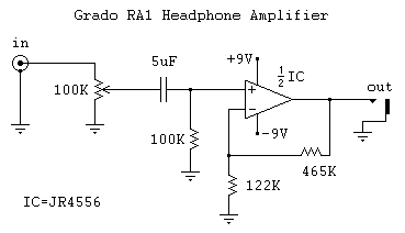
An opamp could be used but would be a non discrete stage. To get the slew rate necessary to drive a output stage transistor, you would need a bunch in paralell to support the Igd current. Opamps slow down when loaded beyond their limits but still operate ala cmoy.
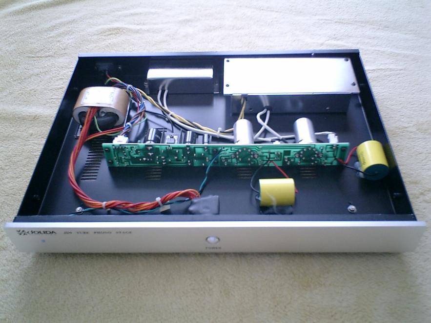
Back to the Jolida, Triode uses an input grid next to the supply rail (B+) cathode. This input gain and bias is set by the input driver stage. As the gain of tubes is similar, they can use one supply rail vs transistors dual rail plus can burn off dc offset and not worry about imbalanced current draw. The Second grid can be set to a bias voltage to help settle the grid to the anode. The filament also helps to settle the input grid to the anode.
Pentode ties both grids to the same bias voltage and relies more on the filament to pull cathode to anode. The input is applied to one of the grids and can be seperated from the other bias grid with RLC network to define the amount of pentode.
Basically a higher bias voltage will allow the tube to produce more gain (power) by limiting the voltage swing or "slew rate". Adding an additional bias grid will increase power but will shorten tube life due to increased material migration. More power will also make a tube become microphonic, reducing the voltage swing will limit how fast a tube becomes microphonic.
Good sturdy tubes overdriven will often just hot spot in a circular fashion or whatever the speaker shape is. This is due to a lack of ion donor material in that location.
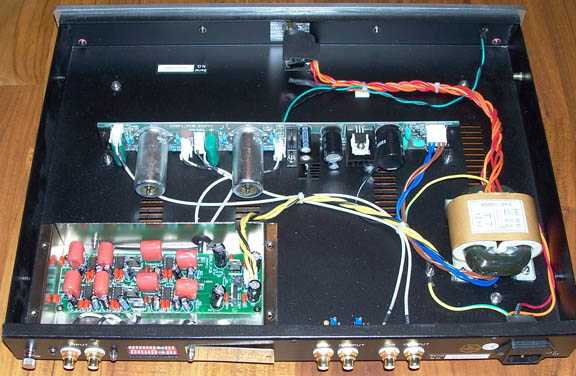
I think you are confusing the discrete transistor voltage reg as cascode. This allows for less B+ caps to be used. This allows the amp to let the recorded music define the note rather than the playback location define a "downmixed" version of the note.
This is the major reason to master music so that a strange rig can be meaningfully played back on a "standardized system". The "primarily" saturation makes the diff between a B movie or music and pro grade. AKA less of that feel of metallic taste after coming down from Crack/Cocaine and or LSD. Also microphones are wayy more sensitive than human hearing. People like to stare at their systems and not look for non existant components. All my components actually play music regardless of if they are speaker or not.