Par-metal group buy: MMM case
Mar 3, 2005 at 9:18 AM Post #46 of 184
ok. option with psu is back in

btw: i'm constantly updating the first post. please keep looking there to see what are current issues are to settle.

here they are:
1. slits on top or not? if so, exactly where? (i.e. how far from side?)
2. height of case? it seems that we'll have the same height on option A and option B. should we go with standard 2" or up it to 2.25, 2.5, or 3"??
3. color(s): what is most preferable? annodizing has been strongly reccommended on account of poor paint job results from par-metal.

folks: basically those three questions is IT, and then i can start accepting $ and ordering. let's try to hammer this out quick so we can get this order going.
 
Mar 3, 2005 at 9:26 AM Post #47 of 184
I'd be more interested in the small (PSU-less) custom case, myself, but I'd probably be in for a custom case either way. I would also prefer 2.5" over 2" or 3".

As for the top slits... really, I don't care where they are so long as they exist. I'm not at all comfortable with no ventilation slots on the top, but I'm fine with ventilation slots down the center.

No real opinion on color. Anything is fine with me there, really.
 
Mar 3, 2005 at 11:49 AM Post #49 of 184
Quote:

Originally Posted by uzziah
1. slits on top or not? if so, exactly where? (i.e. how far from side?)


If you print out this M³ PCB silkscreen layer PDF, it should come out in actual size. Do a sketch of the case (position the board centrally for a narrow, PSU-less case, or for a case with PSU, position the board toward the right), you should be able to easily determine where the top vent slits should go.
 
Mar 3, 2005 at 12:03 PM Post #50 of 184
Quote:

Originally Posted by tangent
Um, if this was a problem, don't you think the STEPS would interfere with itself? Why, if this is the case, do I see such small amounts of ripple in testing?


The output impedance of the PSU voltage regulator is very low and is further filtered with capacitors, so it's not very susceptible to the radiated field from the power transformer. However, this is not true for the input section of the amp, especially with the volume control set to a low position. Thus, if the power transformer is close to the amp board we run the risk of getting low levels of hum.

Indeed this is a problem with the SDS Labs amp pcb. The power transformer is on the same board as the amp, and the opamp + input circuitry is in close proximity to it. In RMAA tests I can see some alarming spikes at 60Hz and its odd order harmonics. In fact with sensitive low-Z headphones you could hear the hum.

RMAA tests of the M³ shows no such problem when the PSU is a good distance away. With my bench supply, if I move it close to the amp I begin to see hum spikes in the spectrum.
 
Mar 3, 2005 at 12:28 PM Post #51 of 184
is it possible to shield the psu within the case from the amp ? mu metal is far to expensive, would a divider plate made of steel or aluminum be sufficient ? Or a small case within the case dedicated for the transformer, tied to earth or ground ?
 
Mar 3, 2005 at 1:51 PM Post #52 of 184
Since the stray field from the power transformer is magnetic, only something like mu-metal would really be effective as a shield, but an aluminum or steel divider should still be better than nothing (as a shield against electric fields). They key to eliminating the likelihood of hum induction is to keep a good distance between the transformer and the amp's input section. Fortunately, the STEPS uses a toroidal transformer and it leaks only a small amount of stray magnetic field. EI-core transformers are much worse, but they tend to leak magnetic field in certain directions, so if you use a psu with an EI-core transformer, you may need to play with its mounting orientation to minimize hum.
 
Mar 3, 2005 at 3:55 PM Post #53 of 184
Keep in mind that the anodized aluminum cases from Par Metals are not intended for shielding. The anodized layer is non-conductive, so the panels are not electrically connected. I sanded off the anodizing around the screw holes to make sure all of the panels were electrically connected (including the divider plate). I haven't experienced any noise/interference problems from the PSU with my PPA, but I have a larger case and used the divider plate. Two cases is probably safest, but I would still recommend making sure all of the panels are electrically connected for the best shielding.
 
Mar 3, 2005 at 5:24 PM Post #54 of 184
tangent: Magnetic interference from transformers is well documented, as amb pointed out. It is easy to demonstrate. Crank the amp volume up with source on pause, and bring your AC power supply near the input section. Note that toroidal transformers tend to have highly directional leakage from the wire egress, so transformer orientation affects the amount of hum.

Keeping the AC power supply outside the amp case is the best solution. Expensive high end preamps use external power supplies, and so should your headphone amp. Relying on physical distance within the case may not be sufficient to eliminate hum. Shielding is a nuisance, and must be done with a ferrous metal such as steel, not aluminum.

amb: steel is much closer to mu metal than aluminum in magnetic shielding performance and is perfectly acceptable for our purposes. aluminum is rather useless, however.

magnetic permeability at 100Hz (lower is better)

.333 aluminum
.260 copper
.027 steel
.011 mu metal

I had a hard time finding those permeability numbers on the web, but am out the door for the day. Perhaps someone with a CRC Handbook can verify them.
 
Mar 3, 2005 at 7:44 PM Post #55 of 184
Quote:

Originally Posted by amb
The output impedance of the PSU voltage regulator is very low and is further filtered with capacitors, so it's not very susceptible to the radiated field from the power transformer.


I'll buy that.

Quote:

this is not true for the input section of the amp, especially with the volume control set to a low position.


So put the power supply on the left, then. All the nodes on the left side of the MMM board are low-impedance. That's the natural place to put it, anyway: it puts the volume knob on the right side, where the majority right-handers want it (if not centered) and it keeps the power wire between PSU output and MMM power input short.

Lots of people have put a STEPS and an amp into the 12x2 inch PAR Metals 20 series case without problems, including me.

Quote:

Indeed this is a problem with the SDS Labs amp pcb.


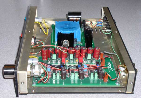
That's a much more egregious problem. There, the separations are a tiny fraction of an inch. It's easy to put a few inches between the amp PCB and the toroid in the case I'm talking about:

tangent-ppa-inside.jpg


There's nearly three inches between the transformer and the PPA capacitor bank in that picture. (No, it isn't a STEPS, but the principle is the same.)
 
Mar 3, 2005 at 11:26 PM Post #57 of 184
Quote:

Originally Posted by uzziah
ok. option with psu is back in

btw: i'm constantly updating the first post. please keep looking there to see what are current issues are to settle.

here they are:
1. slits on top or not? if so, exactly where? (i.e. how far from side?)
2. height of case? it seems that we'll have the same height on option A and option B. should we go with standard 2" or up it to 2.25, 2.5, or 3"??
3. color(s): what is most preferable? annodizing has been strongly reccommended on account of poor paint job results from par-metal.

folks: basically those three questions is IT, and then i can start accepting $ and ordering. let's try to hammer this out quick so we can get this order going.


My vote would be to get the 2.5" tall, 12w x 8d, black anodize, .18" or 0.25" thick front plate, cooling vents on the top near the left and right sides, maybe some on the bottom as well
smily_headphones1.gif


DigiPete

P.S. M³ is going to be my first DIY...mommy!
confused.gif
 
Mar 4, 2005 at 6:31 AM Post #58 of 184
Quote:

Originally Posted by DigiPete
My vote would be to get the 2.5" tall, 12w x 8d, black anodize, .18" or 0.25" thick front plate, cooling vents on the top near the left and right sides, maybe some on the bottom as well
smily_headphones1.gif


DigiPete

P.S. M³ is going to be my first DIY...mommy!
confused.gif


the 20 series front panel is .12" thick. is this not ok? getting a thicker one could be costly, harder to work with, and it would be easier just to leave it at that thickness
 
Mar 4, 2005 at 6:37 AM Post #59 of 184
Not trying to cause trouble, but I was wondering why not go with 2.75" high. From the price list, that is a standard size, so I would think it would be a little cheaper.

I am thinking about option B, depends on the final price. Although, I don't really need the parts around for yet another project to build.
biggrin.gif


One other thing to mention, I think alodine is not conductive, but I always get alodine and anodine mixed up in this regard, so I could be wrong here. One is conductive, the other one is not.

Randy
 
Mar 4, 2005 at 8:23 AM Post #60 of 184
Quote:

Originally Posted by randytsuch
Not trying to cause trouble, but I was wondering why not go with 2.75" high. From the price list, that is a standard size, so I would think it would be a little cheaper.

I am thinking about option B, depends on the final price. Although, I don't really need the parts around for yet another project to build.
biggrin.gif


One other thing to mention, I think alodine is not conductive, but I always get alodine and anodine mixed up in this regard, so I could be wrong here. One is conductive, the other one is not.

Randy


the 20 series is 2"h standard
 

Users who are viewing this thread

Back
Top