


PJPro
100+ Head-Fier
- Joined
- Apr 24, 2009
- Posts
- 155
- Likes
- 10
I've built a handful of headphone amps during my short time in DIY audio including the TangentSoft CMoy, GS DAK Novo and Beezar SSMH as well as a pair of Chip Amp mono power amps (still under construction) with associated ESP soft starts, AMB Labs E24s and ESP DC offset protection. Now I'd like to build something from the ground up.
I'd like to make something simple but a step up from the TS CMoy to drive my RS1s. So, I've been browsing the data sheets to come up with the basis of a design and stumbled across a schematic for a high performance headphone driver in the BUF634 datasheet (fig 5, page 9). I have reproduced this schematic below, adding a pot along the way.
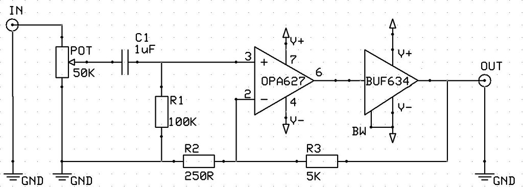
High Performance Headphone Driver
Well, I guess that TI/BB must know what they're on about, right? So what do you think of the above schematic?
I'm assuming that the gain is altered by changing the relative resistance of R2 to R3. I make the gain in the above circuit 20 (R3/R2), although BB report the gain as 21. Ideally, I'd prefer a gain of over 5 but less than 10.
I'm surprised to see that there isn't a resistor between between the opamp and buffer. The TS CMoy certainly had one after the opamp (R5) to reduce noise....although it was optional. I also notice that the M3 also has one between the opamp and discrete buffer.
In fact, (to my inexperienced eyes) there would appear to be some similarities between the simple circuit above and the M3 / PPA circuits except that the above uses an IC for the buffer whereas the others use discrete components. Am I right?
Once the circuit for a single channel is sorted, I intend to use it implement a three channel design. Then I'll consider the power circuit.
Any thoughts, pearls of wisdom or recommendations greatly appreciated.
I'd like to make something simple but a step up from the TS CMoy to drive my RS1s. So, I've been browsing the data sheets to come up with the basis of a design and stumbled across a schematic for a high performance headphone driver in the BUF634 datasheet (fig 5, page 9). I have reproduced this schematic below, adding a pot along the way.
High Performance Headphone Driver
Well, I guess that TI/BB must know what they're on about, right? So what do you think of the above schematic?
I'm assuming that the gain is altered by changing the relative resistance of R2 to R3. I make the gain in the above circuit 20 (R3/R2), although BB report the gain as 21. Ideally, I'd prefer a gain of over 5 but less than 10.
I'm surprised to see that there isn't a resistor between between the opamp and buffer. The TS CMoy certainly had one after the opamp (R5) to reduce noise....although it was optional. I also notice that the M3 also has one between the opamp and discrete buffer.
In fact, (to my inexperienced eyes) there would appear to be some similarities between the simple circuit above and the M3 / PPA circuits except that the above uses an IC for the buffer whereas the others use discrete components. Am I right?
Once the circuit for a single channel is sorted, I intend to use it implement a three channel design. Then I'll consider the power circuit.
Any thoughts, pearls of wisdom or recommendations greatly appreciated.


