A nice(?), simple chip amplifier
Nov 17, 2009 at 10:08 PM Post #31 of 123
Quote:

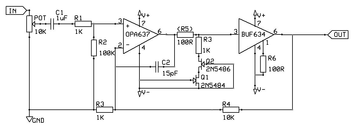
Originally Posted by diditmyself /img/forum/go_quote.gif
1. I think the gain is far to high. You'll have problem adjusting the volume and the amp will be noisy.


OK. I'll tweak the values.
Quote:

Originally Posted by diditmyself /img/forum/go_quote.gif
2. If your source doesn't have DC on it's output (it's probably already capacitor coupled) you dont need the C1 cap. I think an input resistor will do more good.


Need to return to this later methinks.
Quote:

Originally Posted by diditmyself /img/forum/go_quote.gif
3. If you're using a 50k pot, the R1 resistor should be something like 470k to 1M.


OK. Thanks.
Quote:

Originally Posted by diditmyself /img/forum/go_quote.gif
4. A resistor between opamp and buffer might increase the stability. Use something like 47R to 100R.


I'll place it on the schematic as optional.
Quote:

Originally Posted by diditmyself /img/forum/go_quote.gif
5. How the return currents are handled is as important as L/R channels. 3-channel topology, IC-regulators, large and good capacitors - the choice is yours, but make it good. I know what I like but I'm not going to start a war in this thread.


Agreed. I'm intending 3 channel. Thought it best to get a L/R basically right first.
Quote:

Originally Posted by diditmyself /img/forum/go_quote.gif
6. Why not use a PIMETA v2 board? Room for fancy capacitors? With a DC-coupled 3 ch amp, who cares about capacitors!


I didn't realise that the Pimeta used an IC buffer. Having looked, the Pv1 actually uses the BUF634! However, I'd still like to press on as one of my intending learning objectives from this exercise will/may be the production of a PCB (I've never done one before).
 
Nov 18, 2009 at 1:22 AM Post #33 of 123
Try them on a perfboard layout first.

PCB is not something you want to risk unless you're very sure about what you're doing.

The cost of fabricating PCB is not worth the risk. Unless you're loaded, that's another thing lol.
 
Nov 18, 2009 at 1:32 AM Post #34 of 123
Doing a PCB is definitely a case of measure twice, order once.
wink.gif


amb noted something that I have found very useful: Print you PCB layount on paper at 100% scale and make sure everything fits. It will save you from making coasters.

BatchPCB
can make it cost effective to run a single board or two.
 
Nov 18, 2009 at 8:24 PM Post #35 of 123
Thanks for the advice guys.

Yes, I intended to do a protoboard version first to see if it's worth going to the next stage. Printing out the design sounds like a good idea which I hadn't considered.....but then again I'm not going to minimise the layout (like the professionals). But I'll do the print out anyway.
 
Nov 18, 2009 at 8:35 PM Post #36 of 123
Print it out anyways - it helps ensure that the footprint is correct. I speak from experience where I made a whole panel of coasters due the fact that the software had the wrong footprint in it.

And leave it a week between when you decide on your "final" layout and before you send out the job. A week away from the PCB and you may see something you didn't the first time.
 
Nov 19, 2009 at 9:19 PM Post #37 of 123
Well, I've been having a bit if a read and have introduced the spirit of changes to the schematic as recommended.

It now looks like a TangentSoft CMoy with a buffer plugged on the end, with Class A biasing and a cap (33pF) in the feedback loop as used by the M3. TBH, I could arrived almost directly at the design by reading the Headwise Design Paper. Still, it's kept me busy.

I'll post the schematic shortly.
 
Nov 21, 2009 at 12:55 AM Post #39 of 123
You want decoupling caps on the op amps and the buffer. 0.1uF on all supplies and a 0.1uf across the pins as a starting point.

Someone with more experience than me may comment on this one, but I think you want R5 after R3, other wise R5 and R3 form a resistor divider.
 
Nov 21, 2009 at 11:56 AM Post #40 of 123
Well, I was certainly going to place decoupling caps on the power supplies to the opamps (as per the datasheet) but wasn't going to do this for the buffers. Should I?

R5 is optional and serves to reduce noise going into the buffer. Tangent notes that the BUF634 has 200 ohms of series resistance on its input, so R5 isn't really needed. I wanted the option to bung it in, just in case. However, I think you are right, I'll move it to the right of the JFET cascode.
 
Nov 21, 2009 at 7:01 PM Post #42 of 123
From the BUF634 datasheet:

Quote:

Power supplies should be bypassed with capacitors connected close to the device pins. Capacitor values as low as 0.1uF will assure stable operation in most applications, but high output current and fast output slewing can demand large current transients from the power supplies. Solid tantalum 10uF capacitors are recommended.


Nov 21, 2009 at 8:52 PM Post #43 of 123
Quote:

Originally Posted by TzeYang /img/forum/go_quote.gif
biggrin.gif
why not just build a PPA V1/PIMETA V1?


Well, it's true the schematic is more or less the same but I'd like to have a go at producing my PCB. I thought an opamp based design would arrive at the best sounding, simple design. But I wanted something more than a CMoy variant, hence the buffer.

The guidance given here, plus the other posts I've read (here, Headwise & diyaudio) have lead me to produce a PIMENTA / M3 (with an IC buffer) clone. Perhaps it is not surprising given the influence these designs have made on the diy community. And I can take some comfort in the fact that the heritage of the above design is good and should produce a decent amp if I can get everything else right (gulp).
 

Users who are viewing this thread

Back
Top