Quote:
Originally Posted by Miller-8 /img/forum/go_quote.gif
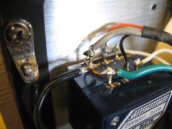
LOL mine isnt as neat as that, mine is a mess. I've only just started soldering. Anyway i tried to undo that chassis screw that you connected the ground to but it wont budge, so I've just slotted the ground wire into the crevice in the corner where the metal folds over.
Hum is greatly reduced now and volume of the music is louder again, hmm.
|
Well I can't take all the credit for the solder job on the Alps. My father did all of the connections on it. However, I am the one who soldered the ground wire after I pretty much taught myself how to solder on PCBs. It's as simple as pie now!
You just have to make sure to keep a little fresh solder on the tip of the iron so it will transfer the heat to your work efficiently, and also wipe the tip off on a wet sponge or paper towel every once in a while.
For that ground connection, try to use a slightly larger screw driver with a larger handle and brace the face plate in the palm of your other hand, push into the screw really good, and try to unscrew it. It's a bit of a pain, but should come loose.
I'm not sure why the music got a little louder from adding the ground though.
Quote:
| I think next I shall attempt to replace the output and input resistors, and also the input caps. Bit worried about touching things though will doing any of that put me at risk of a shock from the power supply caps? |
YES!! You will be in danger of shocking yourself!!
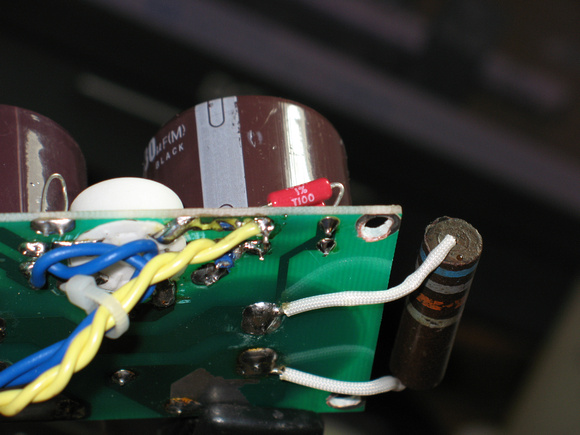
Before you do anymore mods, you should FIRST put a 2 watt bleeder resistor on one of the PS caps. I went with a single 68kΩ resistor on one PS cap, but
dcheming went with two 42kΩ resistors, one on each PS cap. I think dcheming did his that way just because he likes symmetry. I went with just one because I didn't have any other resistors big enough and because my father said that both of those caps are tied together in parallel anyways, so one is all that's really needed as both caps will get discharged regardless.
This single 68kΩ resistor bleeds off all stored power within a few minutes time, but I usually let it sit for about 10 minutes or so just to be on the safe side. I'm usually getting the soldering iron and tools ready durring this time.
Quote:
| Also the input caps I notice some people put jumpers in their place is that safe to do? How can I tell if my DAC is putting out any DC? What happens if I put in jumpers if there is DC leakage? Would I get a hum noise or something more serious? |
Dcheming would be best to explain this one. Honestly, I can't even remember if you put the DMM on "mV" or just "V" when testing your source (DAC in your case) for DC output. I lost all my notes in my PMs for this entire subject when dcheming and I were going over it for my amp. I'm not even sure what the effects would be if there was any DC present. It would be straight DC, so I doubt it would be 60 cycle hum. Maybe something that overloads the input and possibly blows your cans? Since it's DC (Direct Current), it would possibly push the headphone's drivers in one direction and leave them there, burning up the voice coils in seconds?? I honestly don't know.