Using Schiit DAC card module as 'USB Sound card'
Jun 28, 2021 at 10:02 PM Thread Starter Post #1 of 6

Mightygrey

Headphoneus Supremus
Joined
Jun 30, 2016
Posts
1,642
Likes
1,603
Location
Sydney, Australia.
Hey guys, hoping to get some pointers from your collective heads and experience on this one!

Due to using an external DAC (Bifrost 2), I don't really have much use for the Multibit card that came with my amp, so I'm hoping to put it to use in a DIY project. What I'd like to do is use it as a USB input in an all-analogue amplifier, and route the analogue output of the DAC card to the single-ended RCA inputs of the amp.

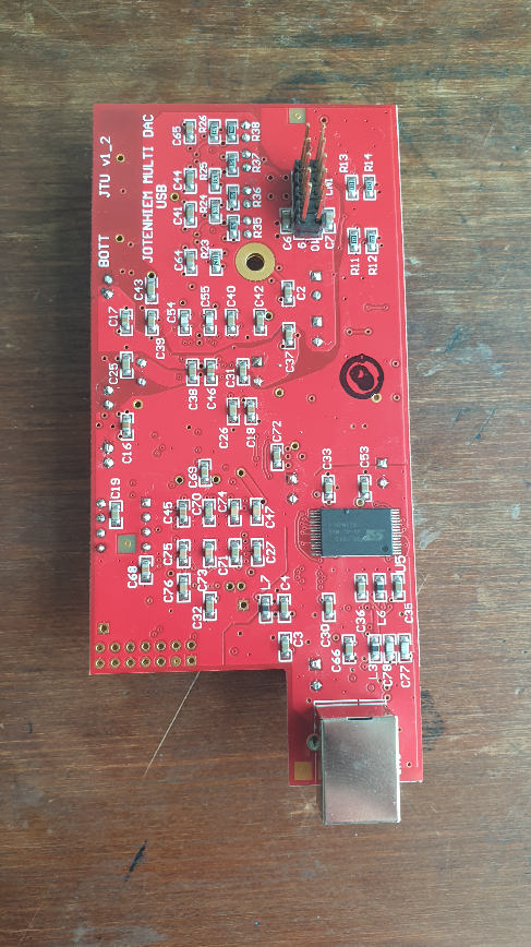
Here's what Schiit's Multibit DAC card looks when removed from the chassis of a Lyr/Asgard/Jot/Rag etc:
1624931248272.png


1624931460485.png


Here is the underside of the card, for reference:

1624931517427.png


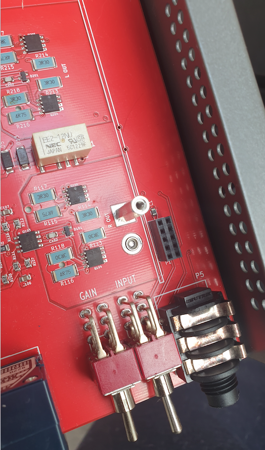
The card is connected to the amplifier PCB board using the dual-head 10-pin connector, shown produding out of the DAC card, and fits into the corresponding female 10-pin connection on the amp:
1624931484867.png


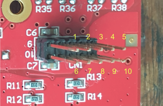
I'm not certain how I can test the outputs on the 10-pin male connection of the DAC card to understand what pins (or combinations of pins) are L/R and ground.
1624931907763.png


The DAC card is USB bus-powered, not mains powered. Using a digital multimeter set to measure resistance (ohms), it is reading that there is resistance between pins 1,4,5,6,9,10 (any combination of these with one another). There is no resistance in pins 2,3,7,8.

Setting the multimeter to DC and playing a 60Hz test tone into the DAC card, there is a small negative DC voltage measurement in pins 3 and 8, when the black terminal is set to the screw hole on the PCB board (which I'm guessing is ground) and the red terminal is applied to each pin. I am unable to detect any AC voltage when using the same method.

If anyone has any pointers I'd be extremely grateful!
 
Jul 1, 2021 at 1:09 PM Post #2 of 6
Let's start with the easy part: The connector looks to be a standard header. The pins should be 0.025" square and on 0.100" pitch. The mating connector could then be a Wurth 61301021821, Samtec SSQ-105-01-T-D, or Preci-dip 803-87-010-10-012101, all of which are available at Mouser Electronics. If you ever want to find something similar, the path is Connectors -> Headers and Wire Housings. Then select 10-position, 2.54 mm pin pitch, 2.54 mm row spacing, two rows, female.

To use the DAC card you'll need to determine the pinout of that 10-pin connector. You could simply ask Schiit for it. They may not provide it, but they can't tell you no unless you ask. It's also not like you're asking for the full schematic.
Alternatively you have to reverse engineer the pinout. I would expect the connector to provide these connections as a minimum:
  • Positive analog supply
  • Negative analog supply
  • Analog ground
  • Positive digital supply
  • Digital ground
  • Relay supply (maybe; the relays on the DAC card are 24 V types (indicated by the -24NU suffix in the part number)
  • Left signal out
  • Right signal out
  • Signal ground
I'm sure there'll be an analog supply. The reference for the multiplier in the DAC will need to come from somewhere and the opamps in the I/V converter will need power. So I'd expect to find something like ±10 to ±15 V somewhere. You could probably find those if you power up the rest of the amp, connect the negative probe of your DC voltmeter to ground (RCA shell), and probe each pin in the female connector with the positive probe of your voltmeter. A piece of component lead clipping can be handy for this. Note any voltages you find.
Then you need to find ground. There should have darn near zero ohm resistance from each ground pin to an RCA shell.

Getting the DAC to output the signal could be tricky. You probably need to get the relays on the DAC board to engage. I would probably mount the DAC board in the amp and see if I could find some clues in the voltages on the 10-pin connector with and without the DAC selected as the input. You can also measure the voltage across the relay coil (the two pins that are off to one end of the relay) to see when the relay engages. They could be mute relays that engage automatically or they could be activated by the rest of the amp. I don't have any experience with this amp, so I don't know.

Best of luck. I hope you'll let us know what you find.

Tom
 
Jul 5, 2021 at 7:39 PM Post #3 of 6
Let's start with the easy part: The connector looks to be a standard header. The pins should be 0.025" square and on 0.100" pitch. The mating connector could then be a Wurth 61301021821, Samtec SSQ-105-01-T-D, or Preci-dip 803-87-010-10-012101, all of which are available at Mouser Electronics. If you ever want to find something similar, the path is Connectors -> Headers and Wire Housings. Then select 10-position, 2.54 mm pin pitch, 2.54 mm row spacing, two rows, female.

To use the DAC card you'll need to determine the pinout of that 10-pin connector. You could simply ask Schiit for it. They may not provide it, but they can't tell you no unless you ask. It's also not like you're asking for the full schematic.
Alternatively you have to reverse engineer the pinout. I would expect the connector to provide these connections as a minimum:
  • Positive analog supply
  • Negative analog supply
  • Analog ground
  • Positive digital supply
  • Digital ground
  • Relay supply (maybe; the relays on the DAC card are 24 V types (indicated by the -24NU suffix in the part number)
  • Left signal out
  • Right signal out
  • Signal ground
I'm sure there'll be an analog supply. The reference for the multiplier in the DAC will need to come from somewhere and the opamps in the I/V converter will need power. So I'd expect to find something like ±10 to ±15 V somewhere. You could probably find those if you power up the rest of the amp, connect the negative probe of your DC voltmeter to ground (RCA shell), and probe each pin in the female connector with the positive probe of your voltmeter. A piece of component lead clipping can be handy for this. Note any voltages you find.
Then you need to find ground. There should have darn near zero ohm resistance from each ground pin to an RCA shell.

Getting the DAC to output the signal could be tricky. You probably need to get the relays on the DAC board to engage. I would probably mount the DAC board in the amp and see if I could find some clues in the voltages on the 10-pin connector with and without the DAC selected as the input. You can also measure the voltage across the relay coil (the two pins that are off to one end of the relay) to see when the relay engages. They could be mute relays that engage automatically or they could be activated by the rest of the amp. I don't have any experience with this amp, so I don't know.

Best of luck. I hope you'll let us know what you find.

Tom
Or, sell the card on.

I'm always interested in the ingenuity of humans.

"I saved $100, and it only requried 100 hours of my time".
 
Jul 5, 2021 at 7:45 PM Post #4 of 6
Or, sell the card on.

I'm always interested in the ingenuity of humans.

"I saved $100, and it only requried 100 hours of my time".
Ha, I hear you. I have the kind of inquisitive personality that gets immense satisfaction from tinkering and tweaking, it's well worth my time, in my opinion. That, and I have plenty of 'inside time' with the current lock-downs in Sydney.
 
Jul 5, 2021 at 8:04 PM Post #5 of 6
The purpose of a hobby is to consume your time. :)

Rather than reverse engineering the Schiit's module, you could consider designing your own DAC. MiniDSP has some nice USB->I2S modules that could be used with a DAC chip: https://www.minidsp.com/products/usb-audio-interface/usbstreamer
Depending on the level of challenge you're up for, you could use a DIY DAC module (many/most of them take I2S in) or you could design your own.

Tom
 
Last edited:
Jul 5, 2021 at 8:11 PM Post #6 of 6
The purpose of a hobby is to consume your time. :)

Rather than reverse engineering the Schiit's module, you could consider designing your own DAC. MiniDSP has some nice USB->I2S modules that could be used with a DAC chip: https://www.minidsp.com/products/usb-audio-interface/usbstreamer
Depending on the level of challenge you're up for, you could use a DIY DAC module (many/most of them take I2S in) or you could design your own.

Tom
Too true Tom!

That particular item looks to be out of stock, the Khadas Tone Board may be an option - I could add panel mounts and extensions for the USB-C + coaxial inputs, and wire the RCA output to a panel-mounted DPDT switch that can select between the DAC and the RCA-inputs.
 

Users who are viewing this thread

Back
Top