Tube Amp + Raspberry Pi + DAC build
Jan 26, 2016 at 6:05 PM Post #16 of 31
That's a lot of metal there. It's probably just sinking the heat. I doubt seriously that anyone would make soldered connection RCA jacks that were not solderable.

 
That makes sense, that's how it felt when I was soldering it. If I recall, I was worried about melting the inside plastic. Also, my soldering iron doesn't have a heat adjustment on it, so I can only get so much out of it. Maybe time for an upgrade? This project is starting to suck away my funds, but I'm coming out of it with a lot of knowledge and a lot of new tools that will last quite a while.
 
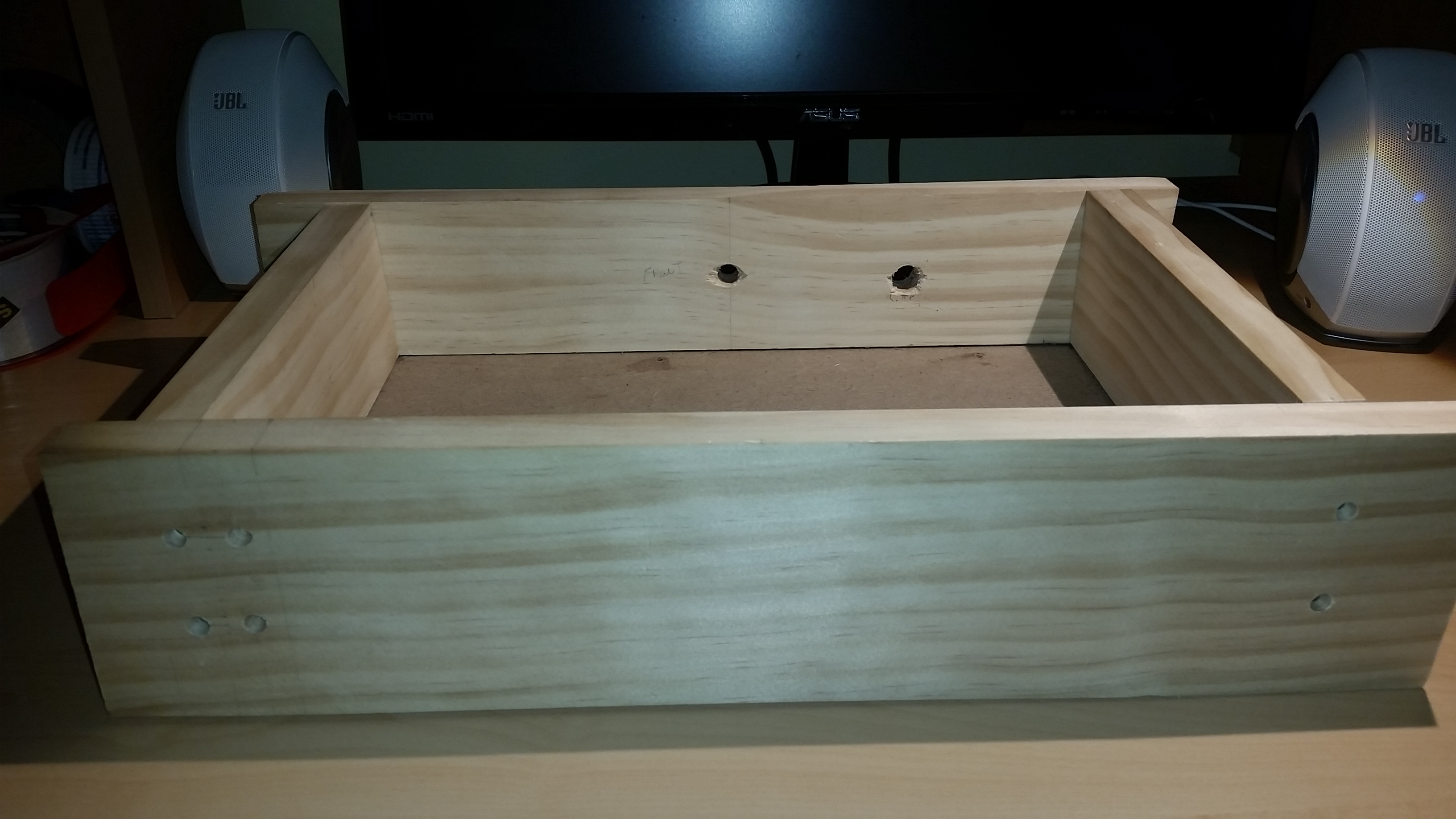
So, I got some more done on the case. The test case is actually going to be pine, not cedar, I misspoke. I'm glad I went this route, as I made a ton of mistakes so far, and I would have been mad at myself if it was with the cherry.
 
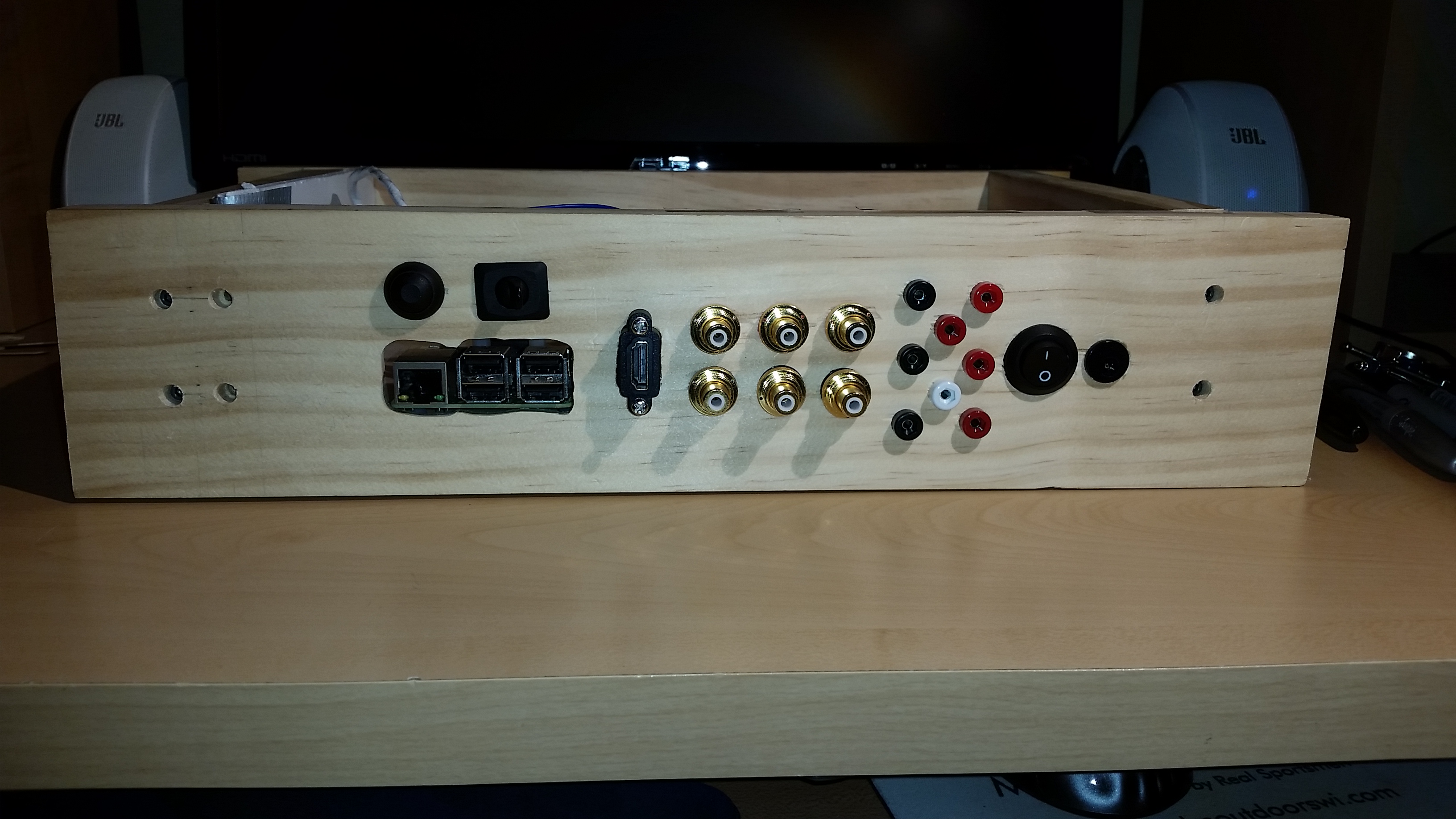
I cut two 15" boards for the front and rear, and two 8" boards for the sides. I only plan on having a ~14 inch wide finished case, but I want to sand down the front face to rounded edges for aesthetics, so I made them significantly longer. I cut 1/4 inch grooves along the lower inside edge for the MDF to sit on. I'm sure there are other ways to do it, but I wanted to try this first. I don't have a router, so I had to make multiple passes with the circular saw. I'm glad I bought the Kreg Ripcut several months ago, as it made this much easier. Still, I invested in a cheap Husky table with a built in router part, plus a cheap accessory to use my Dremel as a router. I will see if I use it much, to decide if I "need" an actual router. I didn't have very straight cuts on the side pieces, as it was my first time using the Kreg tool, so I went to sand them down. Doing it by hand wasn't cutting it, and this isn't really a job for the orbital sander. The fiance heard me lamenting, so she told me to go buy a new tabletop sander, which was pretty cool. My first time using the sander, I wound up taking too much off one side piece, so I had to recut it anyway, and it came out much better that time. I had already cut the MDF down to 12x8, which is what I wanted my final inside dimensions to be. I didn't take into account the grooves, so now I have to recut a new piece of MDF, about 8.5 x 12.5 this time. Before I realized this, I started screwing the case together (see below) with the MDF fit perfectly in place. So now I will need to drill new holes on at least one side, as it is only ~11 inches wide due to the MDF being in the slots. I hope this is making sense, as there is not a real good way to explain this.
 
When I was making the first cuts, I noticed my saw was very dull, so I went to buy new blades, one for fine work this time, instead of a "general" blade. While I was at the hardware store, I looked for some good screws. I don't want to glue this whole thing together, in case I need to take it apart. So I was looking for an EZLok style threaded insert. I remember seeing Adam Savage from Mythbusters using something like this when building his "Traveling Beaver Case" (check out the Tested youtube channel for some more good stuff from him.) They had something similar, but when I went to screw them in, a combination of the hole being slightly too small (my fault) and the quality or thickness of the metal near the screwdriver slot (not my fault) caused the tabs to break off when they were about 90% in. I ordered some actual ones from Amazon, so I will try those out when they get here. I also found some hex socket head screws which look great, although they take forever to screw in due to the fine threads needed for the small EZLok parts. Even though it's a case of form over function, I won't be taking this thing apart very often (hopefully!)
 
I ordered some more wire from Navships, glad to see he is still in business. This time I got a green 24 AWG wire for ground for the audio jacks (I already have two other wires for signal.) I also bought some 20 AWG two conductor twisted pair for the power wiring throughout the case. I think it will clean it up, as I have multiple things going on inside for this build. I bought a set of terminal blocks as well to clean up the power wiring. 
 
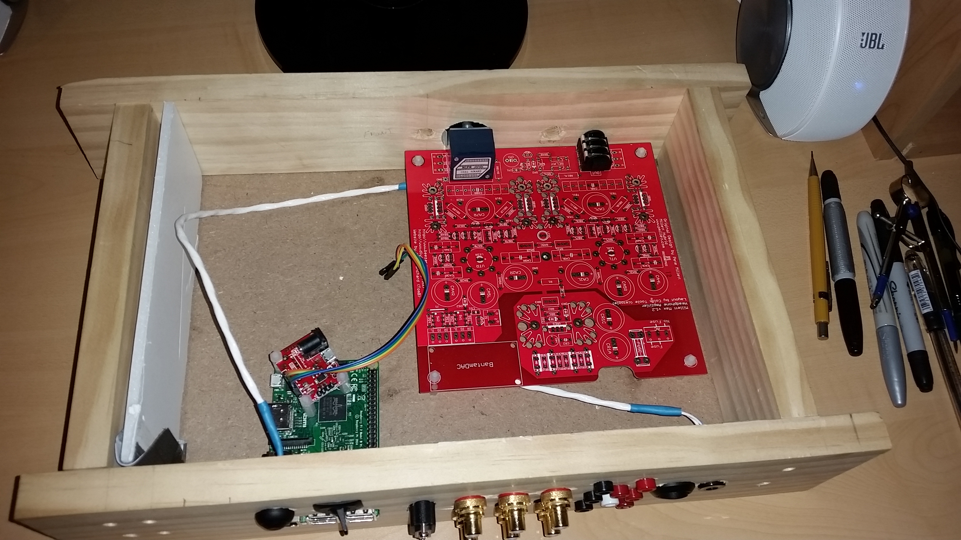
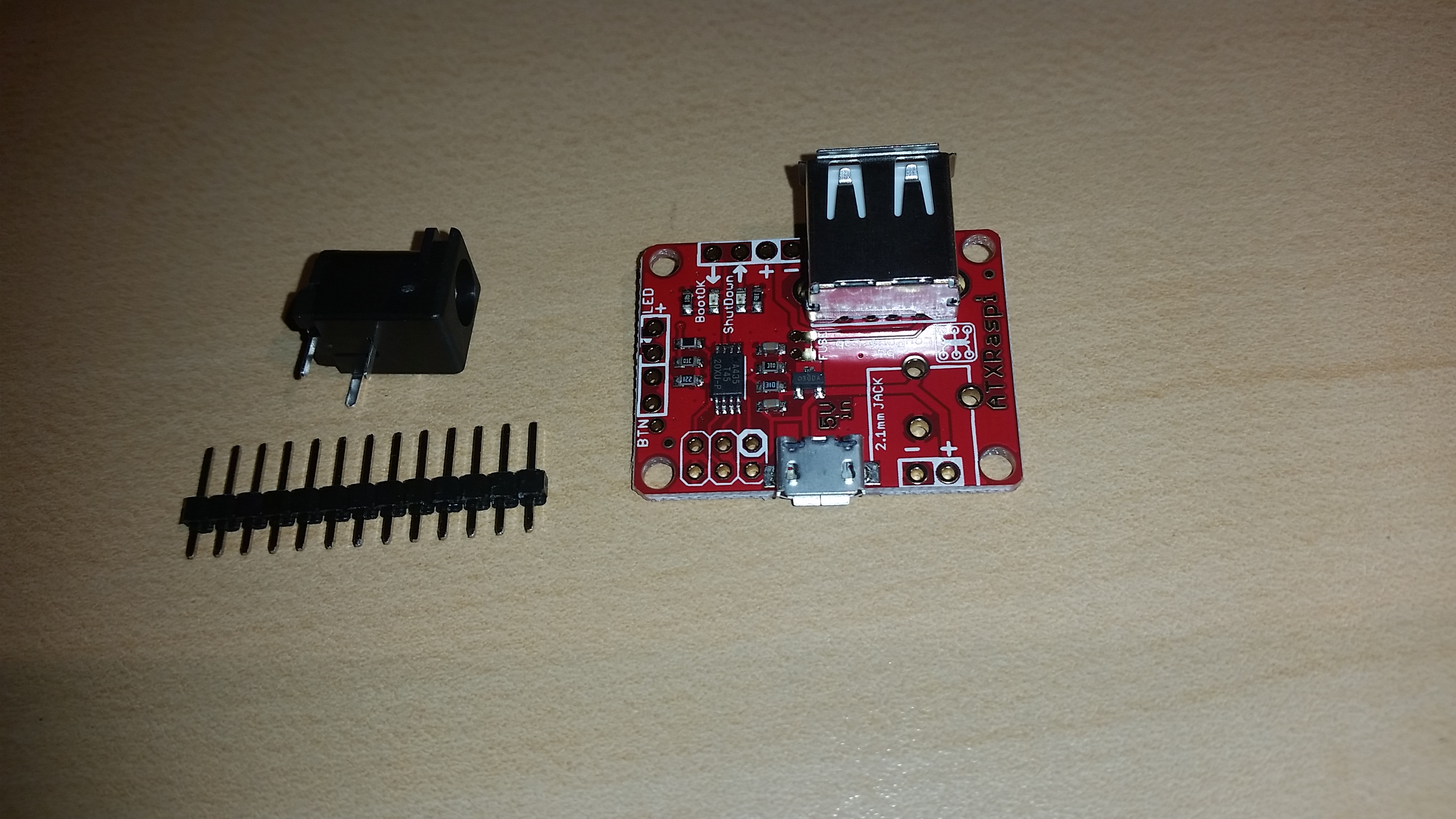
For power to the Pi, I bought a RaspiATX board. The Pi board should not have the 5V just shut off due to concerns with corrupting the memory. People do it all the time, but I thought better safe than sorry. This board uses an Off-Mom button (I hope) to control shutting down or rebooting the Pi. The downside of this is that my AC/DC-DC converter now has to have power to it all the time. Also, I had to find a new button that matched the look and feel of my other button, not an easy task if you are picky. Still, Digikey's catalog is much easier to navigate than I remember, which helped. I also bought test jacks from Digikey. I didn't use the ones from the BOM, as those look a little harder to get a good solder joint, but I got a similar part. For the RaspiATX board, I also needed to buy Raspberry Pi GPIO header jumper wires, and header pins. I could have just soldered directly, but I like the idea of all the components of this build being modular so that replacing anything is not too great of a task.
 
I did a little research into Volumio with an LCD or touchscreen display. While version 2 should be compatible with the Raspberry Pi foundation 7" touchscreen, that doesn't really fit my (current) design (maybe mount in the top someday?) The LCD display would be more do-able, but we are back into "custom" territory again, so I'm going to start with getting this base build working before I start adding on more features. More than the ones I have already added, that is. 
wink.gif

 
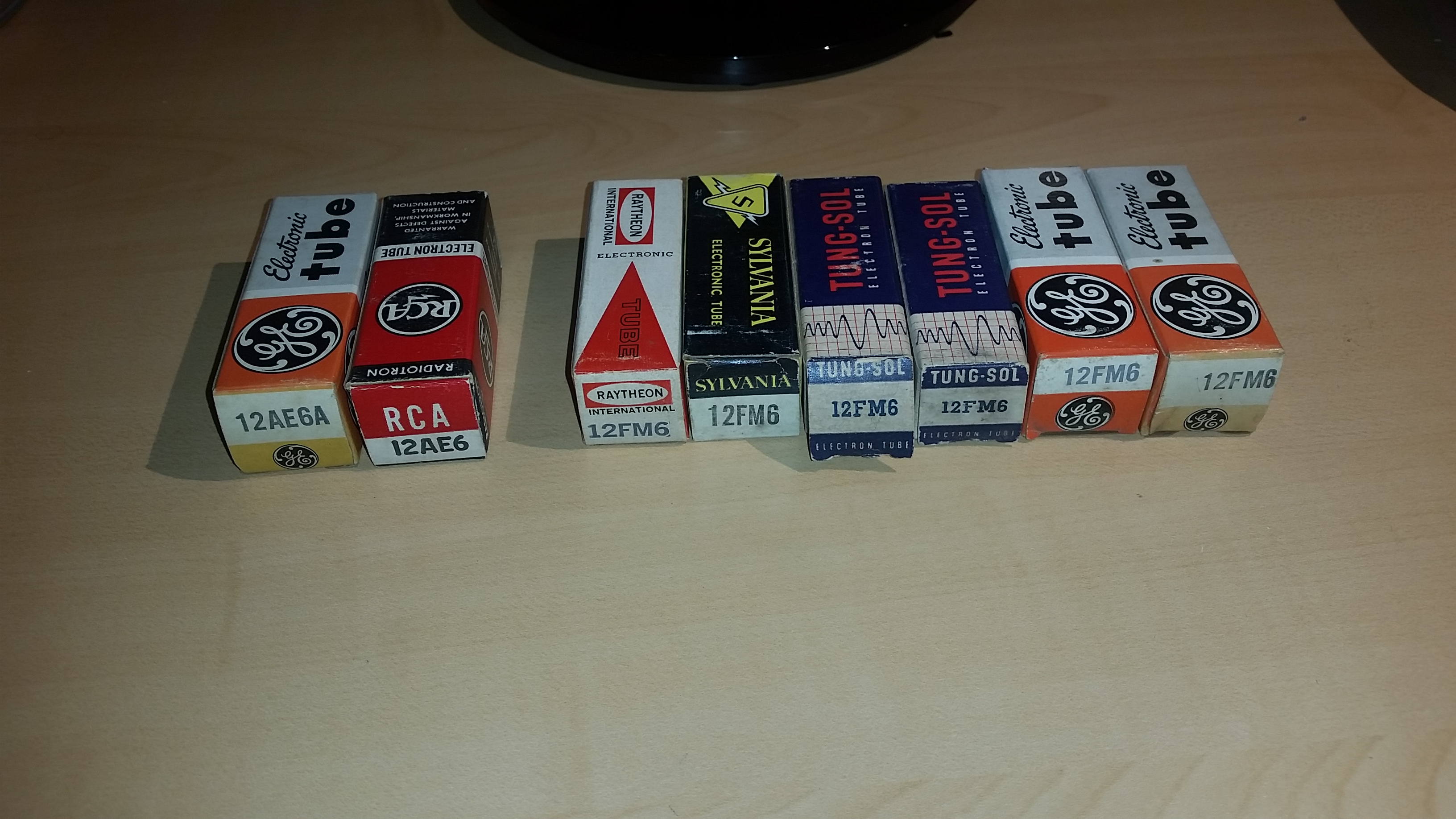
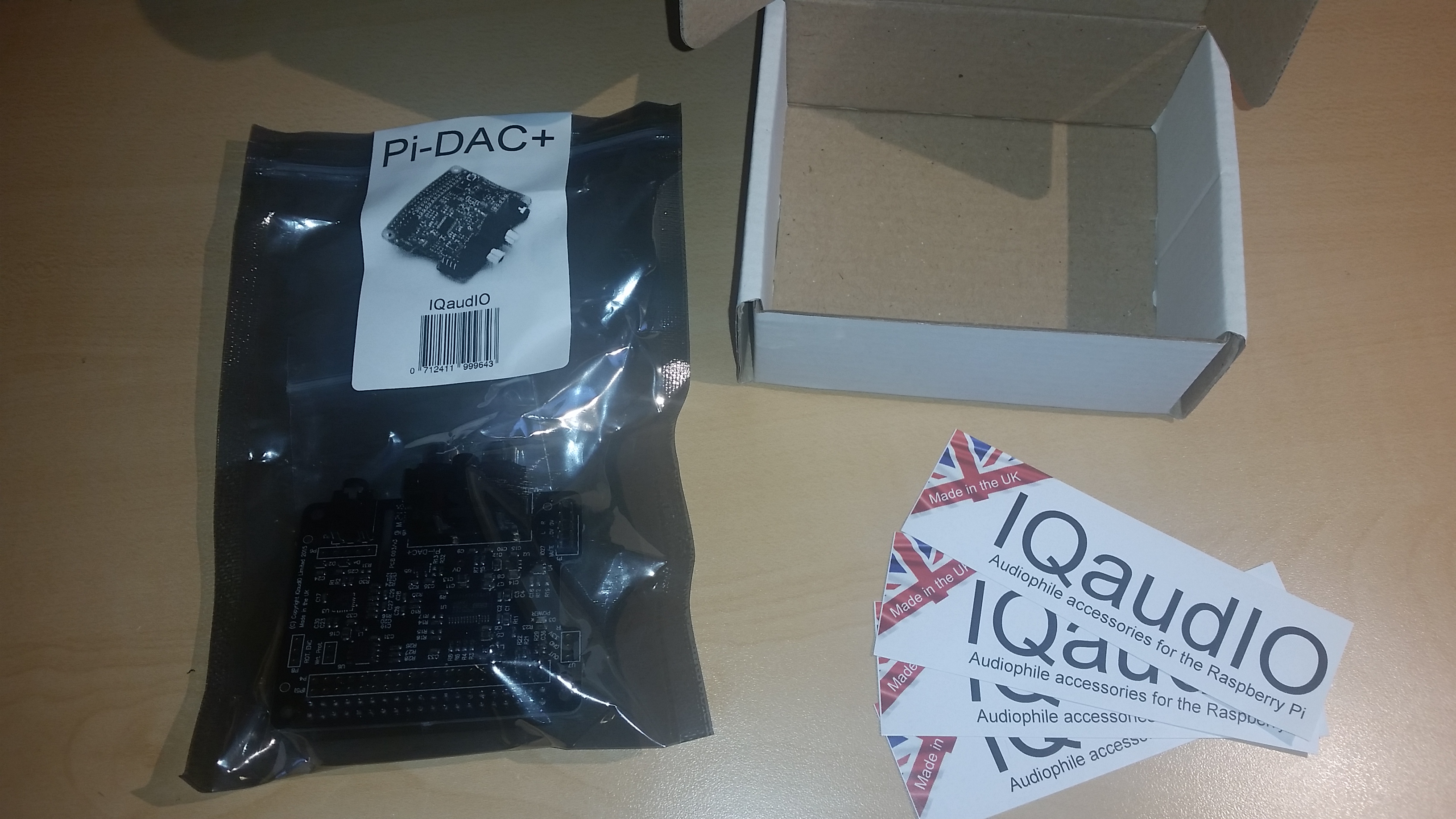
Hopefully I can get a few more things done in the next few days. The Glass Jar Audio kit came and it looks great, packaged well enough to take a bomb blast. Very exciting to get components in the mail again! The IQAudio board has still not arrived yet, and I'm considering buying a "Lite" hifiberry to use as my test subject for this first build, due to cost concerns if I kill a board. Still waiting on my tubes from Beezar, but they are probably in my mailbox now. I'm still going to meet up with the local vendor, just to put some more tubes in the stock pile. He did confirm my suspicions that he gets his tubes from various sources: repair shops going out of business, old stock kept in non-temperature/humidity controlled basements or sheds, etc.
 
That's all for now. I'll try and post some pics of the case later tonight.
 
Jan 26, 2016 at 10:50 PM Post #17 of 31
I use Neutrik bulkhead connectors and cable ends. Great quality. RCA XLR and their PowerCon. Mouser has the entire line.

If your solder isn't flowing to a connector cup use a flux pen first.
 
Jan 27, 2016 at 9:02 AM Post #18 of 31
I bought a flux pen from Amazon that should be arriving tomorrow, but I've never used on before. It sounds like it will be really helpful, if it works as advertised. 
 
I used a Neutrik locking jack on one build, and it did look really nice, but I'm not a big fan of the locks. I know you can disable them though. I looked at one of their long body thru-panel designs that looked great, but it was too long for the board and would run into the caps. Plus my board kit comes with a jack that fits their mounting holes perfectly. What I would like to do if I I could is use a roman ogee router bit to make a nice decorative hole (see image.) The problem is a quality bit from MLCS with a 1/8 shank is $18. Kind of steep, especially if I decide to go with a real router some day, making my 1/8 shank bits a little less useful. Also, I don't know if you can even use a roter bit to enlarge a hole. At least with this style, it looks possble, but I'm not sure. 
 
EDIT:

I just realized that if I buy the dremel plunge router kit, plus the dremel router table kit I already bought, I would be almost to a full size fixed base router. Oh well, live and learn. I would want a plunge router anyway, which would more than double that amount.


Jan 27, 2016 at 11:42 AM Post #19 of 31
Here are some photos. Slowly but surely coming along. Left is case before cutting the grooves, that is what the finished size should be. I plan to put the volume knob right in the middle for aesthetics, even if it is not the most efficient use of space. I also like the idea of dividing the case (not physically) into two distinct sections, giving the whole right side to the Pi and it's associated components.  The RaspiATX board needs to find a spot in there, and I might put power distribution over there as well. Second picture is the kit from Glass Jar. Third picture is after I added the screws for the back panel. I'm curious how they will look once the edges get sanded down, but I think it will look pretty sweet. The holes are countersunk. I don't have a huge selection of countersunk bits, so I had to drill the countersunk hole first, then drill out the side board with a bigger bit for the threaded insert. Notice in the third picture how the sides move in quite a bit from the first picture. That's what I meant about the usable area shrinking due to the grooves. I will hopefully fix that tonight when I cut a new bottom board. That is the next step before starting to cut holes for components. Luckily the mounting locations for the volume knob and headphone jack for the Mosfet Max are in the same place as the Hybrid Max, so I can use that in the meantime before I get my board assembled.
 
I also bought a set of nylon standoffs for the Pi. I would like to mount it to a small separate piece of MDF so it is a little more stable, and insulated in case I line the bottom of the case with aluminum. Plus having it even more modular is nice. The Pi power section can either go with it, or on it's own, separate piece of MDF, not sure yet.


Jan 27, 2016 at 6:12 PM Post #20 of 31
Messed around and learned some basic functions in Google Sketchup. I know this is pretty rough, but I've never really used it before. Just wanted to play around a little bit.


Jan 31, 2016 at 12:56 AM Post #21 of 31
I got a lot of parts over the past two days, so I have been making quite a bit of progress. I think I'm only waiting on two things, a volume knob that's coming "slow boat." And the IQAudio. It has been shown as "At O'Hare in Chicago" since the 1/19 so I don't know what's going on. Paypal is charging my account today, so I'm hoping I don't get screwed. Also, sceleratus was generous enough to offer some pre-cut aluminum for the build (with a badge!) so I'm looking forward to that.

I took some photos of all the parts that have come in. Clockwise from the lower left:

24 gauge Navships wire for audio ground, I already have wire for L and R
Power plugs with pigtails for the RaspiATX. I only need one but 10 were pretty cheap.
RaspiATX
Short USB cable, I don't think I will need this
Panel buttons and switch. The little momentary switch for the RaspiATX/Pi has the best tactile feeling of any switch I have used. I tried to find a DPST switch with this same design for the amp, but no luck.
Test jacks
Two spare AC/DC-DC converters. No idea what kind of quality/lifespan to expect from these things, so I'm glad to have a few spare.
Flux pen
Jumper wires. I plan to disassemble a few of these and replace the wire with the navships wire for audio from the DAC. I really like the idea of everything being modular and that will help so no two devices are soldered together.
Raspberry Pi accessory kit. More pictures included.
5 x 2 terminal strip. One of them arrived broken.
Nylon standoff kits
Fully insulated female spade terminal variety pack for small gauge wire

Not pictured:
20 gauge 2 conductor twisted pair for power from navships

Detail photos of the accessory kit and RaspiATX

The lastest work on the case. My EZ Lok inserts came in so I finished the basic part of the case. No more blue painters tape! Here is how those work, in case anyone is interested.

I used Part 400-006. These were almost too wide for the 3/4" inch thick piece of pine, especially when I wasn't perfectly centered. The package says to use a 1/4" drill. When I tried this, it would not stay centered and was very difficult. Instead, I first used a #12 countersunk bit with 9/64" inside to drill through the front and into the side pieces. This is perfect for a #6 screw (mine are 1 1/4" long for a 1" × 4" piece of pine, which is actually only 3/4" thick.)

After drilling the pilot hole and removing the face board, use a 9/32" bit to expand the EZ Lok hole. After that I used a 5/16" bit to countersink the EZ Lok hole to help center it. If you don't do this, it is a lot harder to get it to go in straight.

When screwing in the EZ Lok, use a stubby screwdriver and go very slow, with even pressure the whole time. I found it best to put the wood on a flat surface with the hole pointed vertically and get eye level with the surface so I could watch it go in straight, making minor pressure adjustments if it started to get crooked.

This was with soft wood (pine) and using a hand drill, not a drill press, and no clamps. You might have better luck but this turned out pretty good for me.

I drilled out a bigger countersunk hole and interior hole on the face board for one, because I thought the insert was in too crooked and would need a little more play, but I think it would have been fine without it.

I spent the rest of the day doing the majority of the back panel layout. I already had the dimensions of the cutout for the Pi, so I built everything off of that.

The first pic is the design on paper. Then I cut out some foam board and redid the layout on there. I cleaned it up a little bit, then a little more, and added the round cutouts. I almost forgot that the initial boxes were the outer dimensions of the audio jacks, which would have been bad. I had only made this one as wide as my internal dimensions, for measurement reasons, so I had to add a backing board to be able to screw the foam to the case. Also, this will help me figure out how to deal with the thickness of the wood I am dealing with. These components are meant for a much thinner material, so I had to make square cutouts on the backing board just to get a few threads. I'm thinking I will find someone with a CNC machine to mill out the wood for me, so I was very careful to document all the dimensions (as you can see.) If anyone has any ideas, let me know!

Next pic is with everything mounted, and an overhead view. Starting to come together!

All I have left are the test jacks, power jack, and the power switch for the amp. I may just bite the bullet and finish the back panel layout, but I'm really sick of design right now. This was hours worth of work, as I'm not very artistically inclined.

I think instead I will work on prepping the internal wiring. You can kind of get an idea of what I'm planing from the overhead view. Once I get a little of the wiring done, I'm going to test out the Pi with the RaspiATX and see how that works. I still have to find the "right" LED for the front (or back?) panel for the Pi and the amp. I usually use these really cheapo looking chrome housings, but I want something a little better. I am debating mounting them on the back, as it might be a little cleaner and cut down on light pollution. But the RaspiATX has some cool features with its LED, so that might be worth having it in front. We will see.

Also, I found out one of my friends has a new 3D printer, which is awesome. I am going to make three interlocking "beds," one for the power distribution and converter, one for the amp, and one for the Pi. I can build the standoffs right into the design and get everything to the perfect position. I am pretty excited, as I have wanted to work with one of these for a while.

Eventually, I should have the volume knob and back panel insert (and badge!) By then, if I have an LED housing picked out, I should be able to finish the front panel.

Oh and I suppose I can get around to assembling the amp at some point too!

I am having so much fun with this build!! I am really glad I decided to take on this challenge, especially with the case design. I'm learning a ton along the way, and I've got this thread to look back on later.

Whew! This is a long post. If anyone else is enjoying watching the build process, I'd love to get some feedback.

Thanks!

Mike


Feb 1, 2016 at 3:13 PM Post #22 of 31
I did a little research into 3D printing and got started with Autodesk 123D. This is so much easier than Sketchup. I made a mockup of the back panel in about an hour, with YouTube tutorials (The Ben Heck Show FTW.) Much less time than by hand. Plus, I was able to model a few different layouts, as I was not 100% satisified with my layout, although it was a good starting point. I'm hoping that I can export into a file that is usable by the CNC company (when I find one) or at least display the measurements so they can put it in whatever software they need to.
 
I did some wiring to get the Pi running for now. I am using RuneAudio right now (so far, I like it better than Volumio) and the ATXRaspi did not work out of the box with the setup script on the product website. I used the instructions found here, making sure to use the "Type=simple" use is referenced later in the page. It works on power up and complete shutdown, but when using the reboot feature, I get some odd issues with the UI and RuneAudio doesn't work. When run via the reboot command manually through a terminal session, it doesn't have any issues once it is started back up. Just starting to look into this now, so no solution at the moment.
 
The navships two conductor twisted pair wire has a very stiff jacket, so much so that I won't use it on this build. I will probably use some red and black wire that I have that is much more flexible. The two wires are joined together by the insulation, so it should still be pretty clean. It is working for now though.
 
When terminating the power jack, I wasn't 100% clear on the diagram and didn't bother to check it with my meter, and didn't think to look at the Millet tutorial. I wired it every possible wrong way before getting it right. For the lazy (like me) the center post goes to the larger of the tabs on the back, the one at 90 degrees to the other tabs. The middle tab is connected to the top tab when the jack is unplugged, but disconnects when the jack is inserted. This one messed me up for a while last night, but I figured it out this morning and moved the wire up to the "top" tab, where it belongs. After terminating and heat shrinking this 3 jack times already, I'm not excited to do it a fourth to change to the other wire. Oh, bother.
 
I finally got the IQAudio DAC board and boy, is it pretty. I ordered it Jan 16th and it showed "at O'Hare" on the 19th, where it stayed until today when it was delivered. It required a signature and luckily I just happened to be home today. It came with a bag of hardware, including a right angle header, which is nice, but I already soldered a header onto the HiFi Berry board, so I'm going to stick with that for now. 1/4 of the header (which includes the power section) is already terminated vertically on the board, but I'm not sure why, or why the rest of the header they supply is right angle. When I soldered the header onto the HiFi berry board, I used an "enclosed" header, as you can see in the pictures, meant for a ribbon cable. I had to trim down the HiFi berry pins in order to get it to fit, and even then it is slightly canted, as I didn't want to trim them too far. Not my brightest moment, as I could have: 1. just soldered the pins I needed, or 2. gotten a "standard," header, with exposed pins.
 
I'm considering a few other options for the Pi. Possibly including a panel mount HDMI connector, in case I want to use it as a full blown media center, or to make it easier to connect a display for troubleshooting. Possibly converting the LAN, USB or both into panel mount jacks, so I can put the Pi wherever I want in the case, and so I don't have to worry so much about mounting height with the 3D print/back panel. Still thinking it over.
 
Pics to follow later.
 
Feb 4, 2016 at 4:16 PM Post #23 of 31
Beezar tubes. It looks like tomb no longer puts the snazzy little stickers on the boxes. I will try and dig out one of my old boxes for fun.
Tubes from my local reseller. He demonstrated to me that the boxes had probably gotten wet at some point by ripping one of the cardboard closure tabs off of the boxes. I'm not sure why he felt that he needed to demonstrate that, or why he thought it was a good idea to damage something I was about to purchase. 
confused.gif

 
IQ Audio packaging
IQ Audio Included hardware
IQ Audio Pi-Dac+ board
Running Raspberry Pi with ATXRaspi. Note how the stiffness of the 2 conductor wire raises the ATXRaspi in the air.
123Design back panel layout. I love this software.


Feb 4, 2016 at 7:16 PM Post #24 of 31
I ruined the color laser printer I was using a few years ago - exactly because I was putting labels through it.  I still use the same graphics on shipping packages, but I cut them out of paper and tape them.  It's kind of difficult to do that on tube boxes and I gave up.
wink.gif
  Sorry.
 
P.S. Check the pins on the tubes you purchased from that dealer.  Getting wet may mean that the pins are corroded as h*ll.  He may have been giving you the reason without totally explaining the consequences.  A wire brush comes in handy - Harbor Freight has some great ones that are very gentle on tubes pins, and they're very cheap, too.  They sell a 3-brush kit for $1.99:
http://www.harborfreight.com/3-piece-detail-brush-set-40439.html
 
Feb 4, 2016 at 11:37 PM Post #25 of 31
No worries tomb! I have had a set in my drawer for several years, so I was used to seeing the splash of color, and wasn't expecting the white boxes. But I will just keep the old boxes around for nostalgia.
 
The one thing he emphasized is that he is very diligent about cleaning the pins of the tubes. I think he said he uses a rubber wheel on a Dremel, and the few that I checked look pretty good.
 
Feb 27, 2016 at 3:23 PM Post #26 of 31
Nice build! I have built several Millet Max over the years, and really enjoyed building them.
I am looking forward to your experiences with integrating the Raspberry Pi into the build, as I just ordered one this week. I was looking for an I2S dac project I could modify to work, but may go with a pre-built one like yours.
 
Mar 6, 2016 at 11:56 PM Post #27 of 31
Thanks! It's kind of Frankenstein-ish right now, but it's a good exercise in the design process for me. I've never been good at design/aesthetics, so I think it's helping me to look at things in new ways.
 
I was out on vacation for a week, but there have been a few new developments. I looked around for a CNC company and found one who would help. I think they quoted me $120, which I think is a little high. Granted, for a "perfect" case, just how I want it, that wouldn't be too bad, but I thought I could do better. While I kept searching, I stumbled across a local technical college that has a "Fab Lab." These are like Makerspaces, only limited to current students. Fortunately, they have a two-session training class that shows you how to use the equipment, and then allows you to use it for the remainder of the semester. Unfortunately, the class for this semester took place a few days before I found it. I got in touch with the professor in charge of the program and, long story short, he is going to set up a special midterm session for me, in exchange for speaking to his students about my job. In the meantime, I sent him the design and he is going to see if there are any adjustments needed.
 
Speaking of design, once I spent some time looking at the paper mockup, I decided to modify the design quite a bit. I rebalanced everything around centering the RCA jacks. Also, I narrowed the case design to 11.5" total, 10" usable, instead of the original 12" of usable space, 13.5" total. This was due to the mid-size CNC at the fab lab only going to 12". I will have to be a little more careful with space, but I think it will result in a tighter package overall. After looking at some of the materials available at the lab, there is something called Sintra that looks to have a great composition, so I am going to start with that as soon as I can. If it goes well, I might just keep it for a second unit.
 
Even with this, I still think it is important to continue with the pine box using my own tools. I just didn't have the tools I needed. I picked up a drill press and a router and was able to get a case to a "functional" state. I've got all the case parts mounted, except one or two (details to follow.) When I drilled out the back panel, I used blue painters tape and a 2x4 backer, and still had blowout on almost every hole, even when using Forstner bits. I think I was using too much pressure, so it's probably a matter of learning to use the tool. With shrinking the design, I had to redrill the two front panel components as well. Now there are two ugly holes where they used to be. Once again, I'm glad I built this first case just for testing. On the front, I went slower and let the bit do the work, and they looked much better. I didn't have a fancy Roman ogee bit for the headphone jack, but even the roundover bit looks pretty good. With the headphone jack just barely fitting through the hole, you can see the volume knob hole is off center, and it is pretty obvious. But If I use a slightly larger bit for the headphone jack, I can hide it.Otherwise, if I remove the "chrome" insert for the jack, that allows me to center the volume knob. I don't know if it's needed for grounding, but I can find out. The thing(s) that are missing from the front are an LED light tied to the ATXRaspi/Pi, or, if I decide to go this route, an LCD screen. I ordered a 20 x 4 screen and I'm going to experiment with it a little before I mess with the case design any more.
 
For the back panel, it is pretty obvious it was my first time using a router. It's not pretty, but it could be a lot worse, and I'm happy with it. There was supposed to be a 1mm post between the USB and Ethernet jacks but it broke off with the router. I also added an HDMI coupler to connect to my TV, in case I add media center software, or for troubleshooting. In fact, I am considering not having the Pi itself exposed at the back, but instead using panel jacks. I purchased the following:
 
USB extenders http://www.amazon.com/gp/product/B00NIH1PZ6
Ethernet extender http://www.aliexpress.com/item/30CM-0-3M-RJ45-Male-to-Female-Screw-Panel-Mount-Ethernet-LAN-Network-Extension-Cable-69081/32367519793.html
 
After trying this HDMI extender http://www.amazon.com/gp/product/B00DHO3DGY
I found the cable was too stiff to bend properly in my case. I decided to go with this HDMI cable http://www.aliexpress.com/item/0-3m-1m-1-5m-2m-3m-5m-Slim-HDMI-Cable-with-Ethernet-1-4-for/32511838581.html
and this coupler http://www.amazon.com/gp/product/B00QHF3VNK
 
I also got this right angle connector in case I need it http://www.amazon.com/gp/product/B002LJNKNM
 
This one too http://www.amazon.com/gp/product/B002K8H7XS
 
So at least I will have multiple options in case something doesn't work. Speaking of multiple options, these components also allow me to consider changing over to the Raspberry Pi Zero if the case dimensions prove to be too difficult to work with. I think I will be fine though, but again, options are good.
 
I think that's all for now. I'll post some pictures when I get a chance.
 
Mar 7, 2016 at 8:06 AM Post #28 of 31
I forgot to mention that the router burned the headphone jack a little. I don't think it will be a problem after I sand and stain. The right hand side of the case (the Pi side) will be smaller. I was using the foam board to simulate where the side will be when I shrink it, although it is not in position in the photos.
 
Keep in mind, although this is really sloppy now, I think it will look a lot better when I get to the final version. This is just a test version to make all (or at least most) of my mistakes on. I just had to put this disclaimer out there, because there are so many beautiful examples of casework that people post here. Hopefully the finished product looks half as good as some of the other builds. I'm just trying to document the whole process, mistakes and all.


Mar 24, 2016 at 12:34 AM Post #29 of 31
Not much to add right now, but I did discover my method for the EZ Lok threaded inserts was wrong. See this video for the correct installation procedure.

https://youtu.be/tIhEqoKE8Dc
 

Users who are viewing this thread

Back
Top