amb
Member of the Trade: AMB Laboratories
- Joined
- Apr 1, 2004
- Posts
- 4,933
- Likes
- 42
Last update: April 25, 2010
News
- April 25, 2010: All future announcements and updates for the LCDuino-1 and related app modules (δ1 relay-based attenuator, δ2 relay-based input/output selector, and others) have moved to the new AMB DIY audio forum. We have an entire forum category dedicated to the LCDuino system, with separate sub-forums for each module. LinuxWorks and I will focus our support of these projects there. We welcome your continued interest and participation.
- Mar 25, 2010: The δ2 (delta2) relay-based input/output selector application modules has been posted.
- Mar 14, 2010: The δ1 (delta1) relay-based attenuator application module has been posted.
Introduction
Ever since I built my β24 power amplfier, I've been wanting to build a high-end pre-amp to match. However, rather than using ordinary rotary switches for input/output selection, and a conventional potentiometer or stepped attenuator based on a mechanical switch for volume, I wanted to do something better.
There are off-the-shelf solutions available for relay-based selectors, relay-based, chip-based or motorized pot volume controls, etc., but virtually all of them are designed for a singular purpose, some are operable with a remote control, some not. Some have a display for status, some don't. It would be nice to have all of those features, yet implement it in an extensible manner such that more capabilities could be added without wholesale redesign, and to allow a builder to tailor the system to suit his/her exact needs.
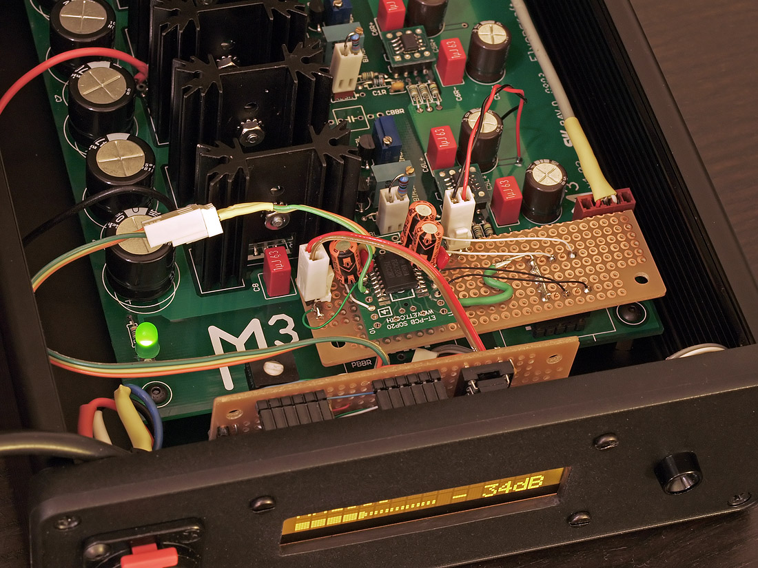
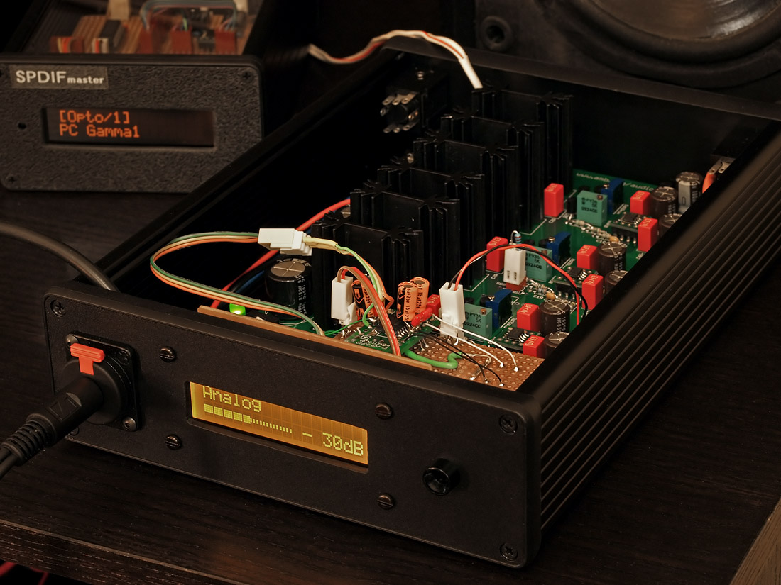
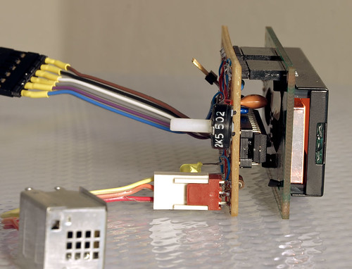
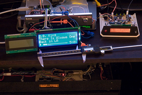
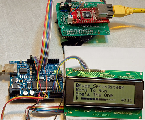
Many of you may have noticed the recent Arduino-based LCD driver circuits that linuxworks built on perfboards, controlling a myriad of devices such as the input/output selector and volume control for his β22, a S/PDIF input selector, and even an Espresso machine monitor/controller. Many months ago we began exploring the idea about turning the basic concept into a generic, extensible and modular platform, usable for many applications not only for audio, but other devices too.
Arduino is attractive because of the rich set of tools, libraries, code and support available for firmware development. It uses the C programming language and the GNU C compiler (gcc) in a nice graphical integrated development environment. The environment runs on Linux, Windows and MacOS X. There is also a large and active Arduino programmer and user community where Open Source is de rigeur. In all it's a very exciting and dynamic scene and fits perfectly with the spirit of our project and goals.
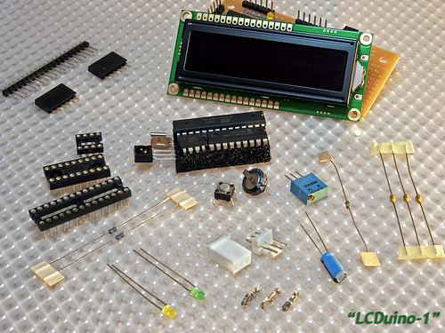
The LCDuino-1
The first result of this collaboration is the LCDuino-1 I/O processor, which will serve as the "heart" of the entire framework.
LCDuino-1 is basically an LCD driver circuit based on a customized Arduino platform with some extra features. This board has two 6P pin headers which will mate up with matching receptacles on an industry-standard 2 row x 16 characters LCD module (80mm x 36mm, parallel interface, 5V DC, low-power backlighting). These LCD modules are available in various colors and backlighting, transmissive or transflective. Here are some examples of usable LCD modules. The LCDuino-1 has the same form-factor as the LCD module, with matching screw hole locations. When mated together, they become a two-board "sandwich" that is easily mounted to an enclosure's front panel. LCDuino-1's slim profile allows the assembly to fit in a 1U rack case. Off-the-shelf front bezels are available for these LCD modules.
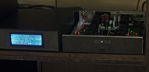
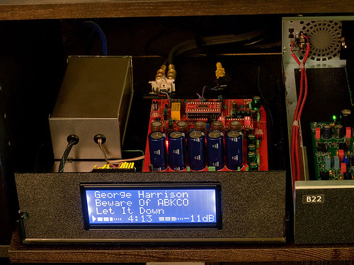
Depending on the nature of the application, the LCD display would show the current input/output selection, a volume control bargraph, the date and time (see below), or some other information as appropriate.
It is worth noting that the LCD module is actually optional, LCDuino-1 could function without one. There may be applications where no display is required, yet LCDuino-1 could still serve as the control center.
The main component on LCDuino-1 is the Atmel ATMEGA328P microcontroller. See the datasheet for chip features, you'll notice that amongst other features, this microcontroller offers many digital and analog I/O ports, I²C serial bus support and serial UART for program download, making it very versatile as a monitor and controller for devices. The microcontroller is clocked by a 16MHz ceramic resonator, and has an onboard pushbutton reset switch should the need arise.
On the LCDuino-1, the I²C bus is connected to an onboard MCP23008 port expander chip, which gives us 8 more I/O ports. Six of these ports are used for controlling the LCD module. This means that we only consume 2 of the microcontroller's ports to operate the LCD module (plus one more port for the backlight). The I²C bus can be extended offboard to other devices (see "Application modules" below).
An optional real-time clock chip DS1302 may be populated (clocked with a 32.768KHz crystal and could be backed up with an optional 0.022 Farad supercapacitor). This allows the LCD display to double as a date/time clock. The real-time clock option consumes three of the microcontroller's ports.
A 3P pin header is provided to connect a Vishay TSOP34838 infrared receiver for remote control purposes. The infrared receiver's output uses up one microcontroller port. The module should be mounted on the enclosure's front panel.
The remaining microcontroller ports are connected to three rows of pads with 0.1" spacing, which could then be connected (via pin headers and receptacles) to other devices.
A 6P pin header allows a FTDI TTL-232R cable to be connected between a computer's USB port and the LCDuino-1 for program download purposes (see below). When installed in the target system, this connector is also where an offboard +5V DC power source would provide power to the LCDuino-1.
There are two LEDs on the LCDuino-1 board, one for power, and another for digital port 13 activity (the latter is customary on Arduino boards). There is also a trimpot for LCD contrast adjustment.
For versatility, a "prototyping area" consisting of an array of through-hole pads with 0.1" spacing allows custom added parts. Pads with +5V DC and GND are located nearby for convenience.
The LCDuino-1 PCB has a low parts count, no SMD parts, and all parts are easy to find. Therefore it's easy and inexpensive to build.
Application modules
The LCDuino-1 itself has enough I/O ports, both analog and digital, to implement simple control and monitoring functionalities. However, such features as input/output selectors, volume controls, etc., require extra hardware. We plan to introduce some or all of the following "application modules" in the future, which will inter-operate with the LCDuino-1:
- Relay based input and output selector
- Relay based volume control attenuator
- PGA2310 based digital volume control
- LDR (light-dependent resistor) based volume control attenuator
- Motorized potentiometer volume control
- X10 power line control
- Possible others
The LCDuino-1 platform and one or more of these "application modules" will be a new, versatile, high performance and extensible way to implement audio and non-audio control functionalities.
In some cases, a separate audio application module allows optimized placement within the system enclosure. For example, the input/output selector and volume control may be installed at the rear, adjacent to the rear panel jacks to minimize audio signal wiring and reduce the opportunity of interference and capacitive-coupling related stereo crosstalk.
I mentioned that LCDuino-1 does not require an LCD module to function, and the motorized potentiometer volume control may be a good candidate to be implemented with no LCD display at all.
Since the firmware will be open source, others are invited and encouraged to use LCDuino-1 as a platform on which to implement their own custom functionality, including more application modules.
Microcontroller programming
There are two steps to program the ATMEGA328P and make the LCDuino-1 functional:
1. Initialize the bootloader
2. Download the program (firmware) code
Both of these require special hardware, the bootloader needs a special AVR programmer dongle and ZIF socket board, and the program code needs to be downloaded with a special FTDI TTL-232R cable. Both need to be connected to the computer's USB port running the Arduino development environment.
I plan to offer pre-programmed microcontroller chips for some "canned" applications, so that builders need neither the special programming hardware nor the Arduino programming environment and firmware source code. Just plug and play.
For those who wish to use LCDuino-1 in a customized manner, then the programming cables and tools will be necessary.
Firmware progress
Linuxworks currently has separate versions of firmware code for each type of functionality that he has already prototyped on perfboard. The plan is to integrate them into a single source code base, add some application module auto-detect capability, and modularize the code to make it easier to understand and maintain.
An integrated code base would also allow a single program to support multiple application modules, so that only one variant of pre-programmed microcontroller chip could support all "standard" application modules.
Other work in progress is to improve the IR remote control support (learning capability, support more brands, etc.).
Schematic diagram
Here is the current schematic diagram of LCDuino-1.

PCB layout
Here is an image of the current PCB layout.

PCB 3D rendering
Here are 3D renderings of the top and bottom sides of the PCB.


Links
- AMB's LCDuino-1 page
- linuxworks audio page
Updates
All future announcements and updates for the LCDuino-1 and related app modules (δ1 relay-based attenuator, δ2 relay-based input/output selector, and others) have moved to the new AMB DIY audio forum. We have an entire forum category dedicated to the LCDuino system, with separate sub-forums for each module. LinuxWorks and I will focus our support of these projects there. We welcome your continued interest and participation.
News
- April 25, 2010: All future announcements and updates for the LCDuino-1 and related app modules (δ1 relay-based attenuator, δ2 relay-based input/output selector, and others) have moved to the new AMB DIY audio forum. We have an entire forum category dedicated to the LCDuino system, with separate sub-forums for each module. LinuxWorks and I will focus our support of these projects there. We welcome your continued interest and participation.
- Mar 25, 2010: The δ2 (delta2) relay-based input/output selector application modules has been posted.
- Mar 14, 2010: The δ1 (delta1) relay-based attenuator application module has been posted.
Introduction
Ever since I built my β24 power amplfier, I've been wanting to build a high-end pre-amp to match. However, rather than using ordinary rotary switches for input/output selection, and a conventional potentiometer or stepped attenuator based on a mechanical switch for volume, I wanted to do something better.
There are off-the-shelf solutions available for relay-based selectors, relay-based, chip-based or motorized pot volume controls, etc., but virtually all of them are designed for a singular purpose, some are operable with a remote control, some not. Some have a display for status, some don't. It would be nice to have all of those features, yet implement it in an extensible manner such that more capabilities could be added without wholesale redesign, and to allow a builder to tailor the system to suit his/her exact needs.
Many of you may have noticed the recent Arduino-based LCD driver circuits that linuxworks built on perfboards, controlling a myriad of devices such as the input/output selector and volume control for his β22, a S/PDIF input selector, and even an Espresso machine monitor/controller. Many months ago we began exploring the idea about turning the basic concept into a generic, extensible and modular platform, usable for many applications not only for audio, but other devices too.
Arduino is attractive because of the rich set of tools, libraries, code and support available for firmware development. It uses the C programming language and the GNU C compiler (gcc) in a nice graphical integrated development environment. The environment runs on Linux, Windows and MacOS X. There is also a large and active Arduino programmer and user community where Open Source is de rigeur. In all it's a very exciting and dynamic scene and fits perfectly with the spirit of our project and goals.
The LCDuino-1
The first result of this collaboration is the LCDuino-1 I/O processor, which will serve as the "heart" of the entire framework.
LCDuino-1 is basically an LCD driver circuit based on a customized Arduino platform with some extra features. This board has two 6P pin headers which will mate up with matching receptacles on an industry-standard 2 row x 16 characters LCD module (80mm x 36mm, parallel interface, 5V DC, low-power backlighting). These LCD modules are available in various colors and backlighting, transmissive or transflective. Here are some examples of usable LCD modules. The LCDuino-1 has the same form-factor as the LCD module, with matching screw hole locations. When mated together, they become a two-board "sandwich" that is easily mounted to an enclosure's front panel. LCDuino-1's slim profile allows the assembly to fit in a 1U rack case. Off-the-shelf front bezels are available for these LCD modules.
Depending on the nature of the application, the LCD display would show the current input/output selection, a volume control bargraph, the date and time (see below), or some other information as appropriate.
It is worth noting that the LCD module is actually optional, LCDuino-1 could function without one. There may be applications where no display is required, yet LCDuino-1 could still serve as the control center.
The main component on LCDuino-1 is the Atmel ATMEGA328P microcontroller. See the datasheet for chip features, you'll notice that amongst other features, this microcontroller offers many digital and analog I/O ports, I²C serial bus support and serial UART for program download, making it very versatile as a monitor and controller for devices. The microcontroller is clocked by a 16MHz ceramic resonator, and has an onboard pushbutton reset switch should the need arise.
On the LCDuino-1, the I²C bus is connected to an onboard MCP23008 port expander chip, which gives us 8 more I/O ports. Six of these ports are used for controlling the LCD module. This means that we only consume 2 of the microcontroller's ports to operate the LCD module (plus one more port for the backlight). The I²C bus can be extended offboard to other devices (see "Application modules" below).
An optional real-time clock chip DS1302 may be populated (clocked with a 32.768KHz crystal and could be backed up with an optional 0.022 Farad supercapacitor). This allows the LCD display to double as a date/time clock. The real-time clock option consumes three of the microcontroller's ports.
A 3P pin header is provided to connect a Vishay TSOP34838 infrared receiver for remote control purposes. The infrared receiver's output uses up one microcontroller port. The module should be mounted on the enclosure's front panel.
The remaining microcontroller ports are connected to three rows of pads with 0.1" spacing, which could then be connected (via pin headers and receptacles) to other devices.
A 6P pin header allows a FTDI TTL-232R cable to be connected between a computer's USB port and the LCDuino-1 for program download purposes (see below). When installed in the target system, this connector is also where an offboard +5V DC power source would provide power to the LCDuino-1.
There are two LEDs on the LCDuino-1 board, one for power, and another for digital port 13 activity (the latter is customary on Arduino boards). There is also a trimpot for LCD contrast adjustment.
For versatility, a "prototyping area" consisting of an array of through-hole pads with 0.1" spacing allows custom added parts. Pads with +5V DC and GND are located nearby for convenience.
The LCDuino-1 PCB has a low parts count, no SMD parts, and all parts are easy to find. Therefore it's easy and inexpensive to build.
Application modules
The LCDuino-1 itself has enough I/O ports, both analog and digital, to implement simple control and monitoring functionalities. However, such features as input/output selectors, volume controls, etc., require extra hardware. We plan to introduce some or all of the following "application modules" in the future, which will inter-operate with the LCDuino-1:
- Relay based input and output selector
- Relay based volume control attenuator
- PGA2310 based digital volume control
- LDR (light-dependent resistor) based volume control attenuator
- Motorized potentiometer volume control
- X10 power line control
- Possible others
The LCDuino-1 platform and one or more of these "application modules" will be a new, versatile, high performance and extensible way to implement audio and non-audio control functionalities.
In some cases, a separate audio application module allows optimized placement within the system enclosure. For example, the input/output selector and volume control may be installed at the rear, adjacent to the rear panel jacks to minimize audio signal wiring and reduce the opportunity of interference and capacitive-coupling related stereo crosstalk.
I mentioned that LCDuino-1 does not require an LCD module to function, and the motorized potentiometer volume control may be a good candidate to be implemented with no LCD display at all.
Since the firmware will be open source, others are invited and encouraged to use LCDuino-1 as a platform on which to implement their own custom functionality, including more application modules.
Microcontroller programming
There are two steps to program the ATMEGA328P and make the LCDuino-1 functional:
1. Initialize the bootloader
2. Download the program (firmware) code
Both of these require special hardware, the bootloader needs a special AVR programmer dongle and ZIF socket board, and the program code needs to be downloaded with a special FTDI TTL-232R cable. Both need to be connected to the computer's USB port running the Arduino development environment.
I plan to offer pre-programmed microcontroller chips for some "canned" applications, so that builders need neither the special programming hardware nor the Arduino programming environment and firmware source code. Just plug and play.
For those who wish to use LCDuino-1 in a customized manner, then the programming cables and tools will be necessary.
Firmware progress
Linuxworks currently has separate versions of firmware code for each type of functionality that he has already prototyped on perfboard. The plan is to integrate them into a single source code base, add some application module auto-detect capability, and modularize the code to make it easier to understand and maintain.
An integrated code base would also allow a single program to support multiple application modules, so that only one variant of pre-programmed microcontroller chip could support all "standard" application modules.
Other work in progress is to improve the IR remote control support (learning capability, support more brands, etc.).
Schematic diagram
Here is the current schematic diagram of LCDuino-1.
PCB layout
Here is an image of the current PCB layout.
PCB 3D rendering
Here are 3D renderings of the top and bottom sides of the PCB.
Links
- AMB's LCDuino-1 page
- linuxworks audio page
Updates
All future announcements and updates for the LCDuino-1 and related app modules (δ1 relay-based attenuator, δ2 relay-based input/output selector, and others) have moved to the new AMB DIY audio forum. We have an entire forum category dedicated to the LCDuino system, with separate sub-forums for each module. LinuxWorks and I will focus our support of these projects there. We welcome your continued interest and participation.