


Soundsgoodtome
Headphoneus Supremus
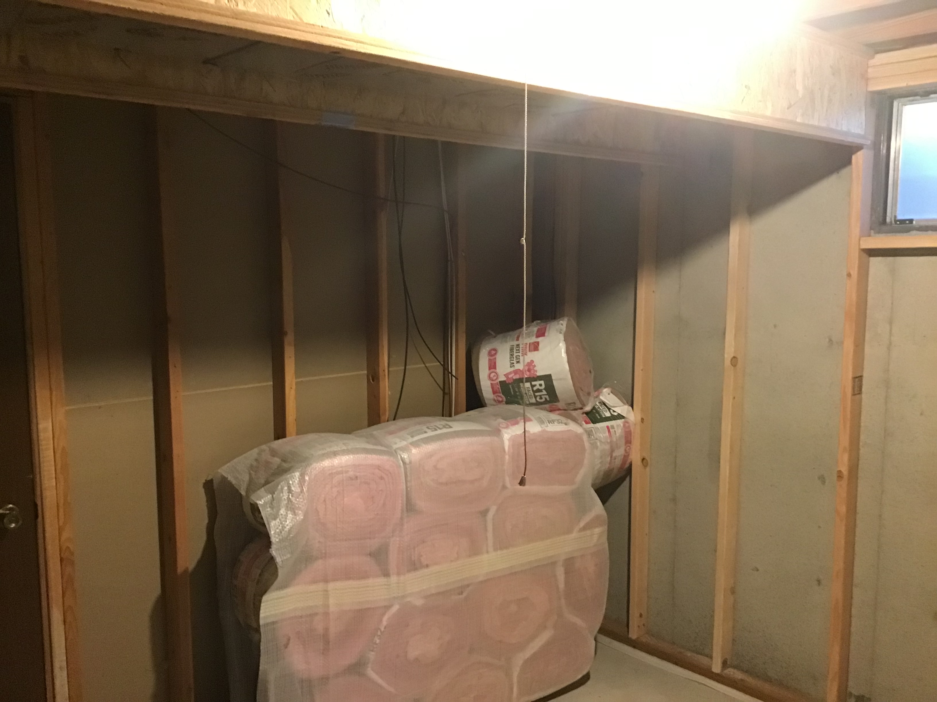
Jj, since the minimeets I've learned that separating the digital circuits to another completely different wiring run as well as "capping" said devices with a conditioner (like a furman ac215a) and having the analog gear on a separate power run to the breaker has yielded good results. I only wish i could've ran both digital and analog circuits with 12 gauge, my digital side of power is only 14g and also powers 4x 10w led bulbs. I figured out of all the gear the speaker and headphone amps are going to be the most thirsty, hence the thicker wire.
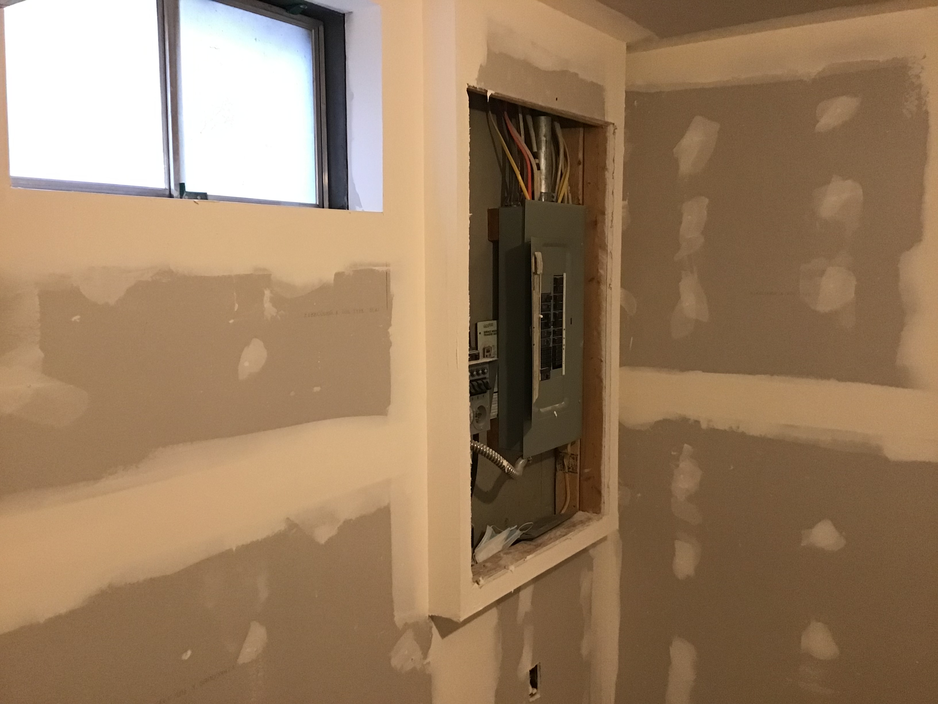
It's actually an easy experiment with an extension cord if you know which outlets are in which lines. A matter of running an extension cord to an outlet on a different breaker.
It's actually an easy experiment with an extension cord if you know which outlets are in which lines. A matter of running an extension cord to an outlet on a different breaker.

