The DIY transformer box thread (for electrostatic phones) (coming up: review on JRM M99B trans)
Sep 13, 2008 at 4:38 AM Thread Starter Post #1 of 100

AudioCats

Headphoneus Supremus
Joined
Feb 25, 2007
Posts
3,726
Likes
264
Location
CO, USA
Lets start a thread on building DIY electrostatic transformer box.

I have one in work since who-knows-when. Never got to finish it up (yet), come to think of it, it is probably because of the ESP950 recable situation (still not fully done, waiting for stax extention cords). But anyway, I am using a pair of JRM M99B 1:50 transformers, originally intended for full size electrostatic speakers, the price was about $120 after shipping.

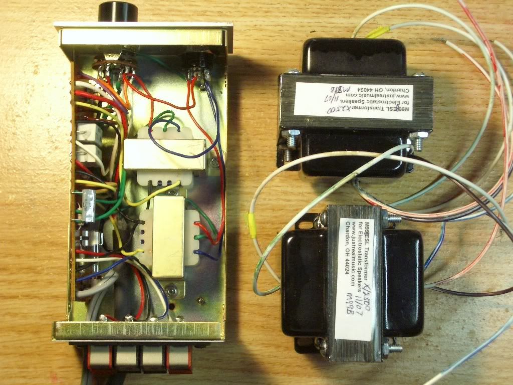
The M99B's are relatively large, the external dimensions are 76mm x 72mm x 64mm (h), weights exactly 2 LB each. Just so you have an idea how much bigger they are comparing to the stax ones, here is a picture of the M99B's next to a SRD-6 box (the transformers in a SRD-7 box are said to be the same as the ones in the SRD-6)....

IMGP1862.jpg


Will post a review after I (eventually) finished the JRM box.
 
 
----- UPDATE: after about 2 years of use, the JRM box developed major channel inbalance (happened over night, about 2 weeks ago). upon trouble shooting, the "quiet channel" transformer's secondary DCR is a lot less than the good one: quiet= 200 ohms vs. good =330 ohms. The quiet channel transformer also gets warm during use (while the good one is cool), also the protector resistor for the quiet channel is hot (while the good channel resistor is cool). Looks like some kind of partial short has developed in the secondary winding.
I will not recommand JRM transformers due to this reliability problem.
 
Sep 13, 2008 at 6:47 AM Post #3 of 100
This is going to be a great thread!
smily_headphones1.gif

I am seriously looking into building a higher quality transformer box myself, and its nice to discuss possible transformers (vendor, model, dimensions, ...).
 
Sep 13, 2008 at 10:57 AM Post #4 of 100
If you're going to really go nuts with this I think an adjustable bias supply and built in power amp (something like a gainclone maybe) would be fun. At least that's what I was mulling over in my head.
evil_smiley.gif
 
Sep 13, 2008 at 12:32 PM Post #5 of 100
Quote:

Originally Posted by AudioCats /img/forum/go_quote.gif
and has anybody done a Stax type box using transformers from a Koss E/9?


Nope but they should work since they have a CT. The ESP10 units do not (not that I've seen at least) which is a shame since they are huge!! Other transformer candidates would be push-pull tube output trafos. Just wire them backwards and an instant transformer that can handle a lot of power.
 
Sep 13, 2008 at 6:49 PM Post #6 of 100
Quote:

Originally Posted by n_maher /img/forum/go_quote.gif
If you're going to really go nuts with this I think an adjustable bias supply and built in power amp (something like a gainclone maybe) would be fun. At least that's what I was mulling over in my head.
evil_smiley.gif


another reason why my transformer box hasn't gotten done, is because of the mutiple bias (it has something to do with the recabling situation). I am using a Neutrik 7 pin outlet allowing up to 3 different bias in one socket. Needless to say there will be a bit of recablings for my phones. The planned voltages are 230, 580, and a selectable, up to 620V.


Birgir, for ESP10 trans without the center tap, can't you just use two 10M resistors aross the output and use the center point as ground? The transformers in my E/9B box have no center taps either (actually, the wire was there but cut flush).
 
Sep 13, 2008 at 7:26 PM Post #7 of 100
Quote:

Originally Posted by AudioCats /img/forum/go_quote.gif
and has anybody done a Stax type box using transformers from a Koss E/9?


I'm working on it.

E./9's vary widely, so your energizer may have a different configuration, but the ones i pulled out of the sad old 220v unit i had here have 1-ohm primaries, and there were 6.8ohm resistors on the board bringing the impedance up to 8 ohms.

Which is weird, but i suppose it's one way of minimizing the reactive nature of of the transformer as a load.

I bought some big sandstone resistors because the original koss resistors were in pretty sad shape.

At the moment my plan is to build an SRD-7 MkII circuit around them on perfboard. This is in addition to my plan of converting one of my SRD-7's to MkII functionality.

The pipe dream with the koss transformers is to max out my M3 headphone amp so that it can drive them directly, and mount it all in a 19" steel chassis that used to be a 24-port ethernet switch. The M3 should be able to push 6 watts RMS into them, which is probably enough.

If not, I'll stick the kossstax hybrid circuit another enclosure and stick something else in the box with the M3.


Quote:

Originally Posted by AudioCats /img/forum/go_quote.gif
another reason why my transformer box hasn't gotten done, is because of the mutiple bias (it has something to do with the recabling situation). I am using a Neutrik 7 pin outlet allowing up to 3 different bias in one socket. Needless to say there will be a bit of recablings for my phones. The planned voltages are 230, 580, and a selectable, up to 620V.


I've been wondering about ways to get 620v for a potential future ESP950 as well. Adding another rung to the ladder in the MkII circuit would add too much. I could have a whole separate ladder with a different zener at it's start, or something. Or maybe have three different zeners selectable with a rotary switch, giving me a final voltage of 580, 600, or 620.

I'm interested in any cheap & cheezy theories on this.


Quote:

Originally Posted by AudioCats /img/forum/go_quote.gif
The transformers in my E/9B box have no center taps either (actually, the wire was there but cut flush).


How flush? I bet you can expose enough to tack a wire onto the stub.
 
Sep 13, 2008 at 8:05 PM Post #8 of 100
I am going the Koss style, using zeners.
The 110~ voltage goes through a 100k resistor to a 8x multiplier to get about 800-900v. The high voltage then goes throught a 200K resistor to a string of zeners. Different voltage can be taken from different location of this zener string. You can basically get whatever voltage you need by doing it this way. of course, there will then be the mega ohm load resistors and high voltage caps.

A zener string has a lot of zeners. My string:
GND+ 91 + 91 + 51 (233v at this point, for low bias) + 51+51 (335v at this point, for ESP7) + 51 + 51 +51 +51 (539v, for a softer pro-bias) + 33 (572v, pro-bias) + 33 (605v, for ESP950, HE1.2) + 15 (620v).
 
Sep 13, 2008 at 8:36 PM Post #9 of 100
Ouch that is a lot of diodes!!
eek.gif
The Gilmore variable bias would also work well if you either feed it from a transformer (300v) or add a stage to it. In stock configuration it only gets up to 500v. A DC-DC converter is a good way but doesn't fit the cheap bastards motive.

Quote:

Originally Posted by AudioCats /img/forum/go_quote.gif
Birgir, for ESP10 trans without the center tap, can't you just use two 10M resistors aross the output and use the center point as ground? The transformers in my E/9B box have no center taps either (actually, the wire was there but cut flush).


That would do it but I've yet to test it. Hmm I should have plenty of 10M resistors...

If you can see the stub then you can use it.
regular_smile .gif
I got away with a few mm's on a Stax power trafo and the amp works just fine.
 
Sep 15, 2008 at 7:21 PM Post #12 of 100
By the way, if one or two people need just one WPI 6 pin socket and can't make the $20 minimum order at allied, I ordered half a dozen and might be willing to part with a couple of them. Plugs too.
 
Sep 18, 2008 at 7:48 PM Post #14 of 100
Quote:

Originally Posted by spritzer /img/forum/go_quote.gif
This one should work just fine for a DIY trafo box if wired backwards. It even has a 1:25 ratio on the 8 ohm tap. With some quality speaker terminals, box and a bias supply it should come in at about 200$ for a complete unit.


Thanks for the link!
This one and the Sowter 4342 seems like strong candidates for transformers for a DIY energizer unit.
 
Sep 28, 2008 at 7:31 PM Post #15 of 100
I'd like to advise anyone following along with my hair-brained schemes that koss E/9 transformers are somewhat fragile.

The secondary windings are connected with the sort of gauge of wire you find on dynamic headphone voice coils, and these are folded over the bottom lip of the plastic bobbin to where they're soldered to the wires that are looped through the top of the bobbin.

And they can, it turns out, easily be severed by letting your extracted transformers knock around the desk for a few weeks.
 

Users who are viewing this thread

Back
Top