Synergy?
Sep 8, 2008 at 4:27 AM Thread Starter Post #1 of 15

Ruahrc

100+ Head-Fier
Joined
Jun 2, 2002
Posts
289
Likes
10
Many reviews and testimonials often speak of two or more components having synergy. What exactly is the basis of this? I can envision a situation in which for example a bass-heavy headphone is matched with a bright amp, and the result is more neutral-sounding than either component alone, however I don't think this is always the case when people state that two components have synergy.

I'm assuming that when people mention the phenomenon they are implying that the sum of the components is greater than the total of the individual pieces, i.e. headphone A is great sounding and so is amp B but when you put the two together it sounds much better than you expected.

Is it that anything which to them sounds good has some kind of synergy? If someone prefers a lot of bass, would they not classify a bass-heavy headphone and a bass-heavy (or at least warm) amp as being synergestic because it more dramatically reproduces the low-end heavy sound that they prefer?

Has anyone ever measured the frequency response or other objective parameters of a "synergestic" system? If so, what was the result?

Just some thoughts for discussion...

Ruahrc
 
Sep 8, 2008 at 6:06 AM Post #2 of 15
Good synergy to me is the sum of two components results in a more favorable sound than using just one component along. By 'more favorable' I mean not just enchantment / improvement, but also flaw reduction / neutral.

The problem of bass-heavy headphone + warm amp combination is it often results in a sound that is lower in resolution and speed, plus overly warm (muddy) bass that affect the mid and treble. If such combination introduces more flaw (muddy sound) than improvement (enhanced bass), than I will consider them to have bad synergy. Vise versa, if the improvement doesn't cause too much flaw (only slightly muddier), than I'll consider they have good synergy, assuming if I am a basshead of course. Of course, if the combination doesn't improve as much as I expected nor introduces too many flaw, I'll consider them to have a fair synergy.
 
Sep 8, 2008 at 7:27 AM Post #3 of 15
synergy to me is when components share similar sound characteristics. in your example, bass heavy fones + bright amp is an approach that's going in the opposite direction of synergy. you are matching gear that at contradicting one another (think tug a war). people are going to argue 'no it balances it out' when in reality you're just mixing two weaknesses and hoping the polar aspects will somehow overshadow it...
 
Sep 8, 2008 at 9:46 AM Post #4 of 15
I think the word 'synergy' doesn't dictate whether it must be an enhancement (strengthening of one kind of character) or an compensation (reduction of coloration / flaw). As long as the end result is favorable to the listener, the synergy is good.

Quote:

Originally Posted by panda /img/forum/go_quote.gif
when in reality you're just mixing two weaknesses and hoping the polar aspects will somehow overshadow it...


..or you can see it as mixing two strengths so the polar aspects can enhance each other for a better end result on the listener's ears.

Whether the glass is half full or half empty, there is still only half a glass of water no matter how we describe it. The important bit is whether you like the water (good synergy) or not (bad synergy).
 
Sep 8, 2008 at 7:16 PM Post #5 of 15
The amount of bass or treble can't be compared between electronics and transducers.

Having an uneven frequency response in a given element is something very different according to the kind of element we're talking about.

In order to get a rough idea, we may say that the maximal deviations are around

+20 dB for a room
+5 to +10 dB for a speaker or for headphones
+1 dB for an amplifier, or for speaker cables
<0.01 dB for CD players or interconnects.

Therefore interconnect, for example, will never balance the coloration of a given pair of headphones.
 
Sep 9, 2008 at 6:12 PM Post #6 of 15
Quote:

Originally Posted by Pio2001 /img/forum/go_quote.gif
The amount of bass or treble can't be compared between electronics and transducers.

Having an uneven frequency response in a given element is something very different according to the kind of element we're talking about.

In order to get a rough idea, we may say that the maximal deviations are around

+20 dB for a room
+5 to +10 dB for a speaker or for headphones
+1 dB for an amplifier, or for speaker cables
<0.01 dB for CD players or interconnects.

Therefore interconnect, for example, will never balance the coloration of a given pair of headphones.


Interesting, do you have a source for these ballpark figures ? They do look more or less plausible, though CD players are not quite as flat as they ought to be - a 0.5db deviation is normal for many CD players especially at higher freqencies, better ones get down to 0.2db or 0.1db. 0.01 looks a bit optimistic as a general rule though I am sure some manage this. None of my players ever managed better than +/- 0.5db. Still far and away the flattest FR you are likely to get in the chain.

I always chuckle when folks comment about this or that CD player having an audible high fequency roll off as

1 , They don't unless this has been engineered in (viz Wadia) and is really severe i.e 3db or more and

2 You cannot hear it anyway as human hearing is just not that sensitive , see 1 above

If you study the FR curves for CD players the abiding pattern is flatness.

Speaker cable deviations are highly frequency dependent and with only one exception I have ever seen they all roll of markedly above 10K
 
Sep 9, 2008 at 7:12 PM Post #7 of 15
The 20 dB figure for a room comes from scarce informations. The speaker shop in my town used to say that they measured a +18 dB peak in a client living room. And one or two readings on the web seemed to confirm this value as a maximum deviation, but I have no documented reference.

For headphones, we have the headphone.com measurments. It has always puzzled me to see that a a given frequency in the treble, the Sennheiser HD600 was 15 dB below the Beyer DT990, which are two high end models.
I compared them in real life, and well, this seems to be right on the spot !

For speakers, I have seen some measurments here and there. It seems that good speakers manage to stay within +/- 2dB in a wide frequency range in medium frequencies. But in low frequencies, this is another story.

Amplifiers are nearly never measured under real load. Resistive loads do not account for their sensitivity to the speaker's impedance. But here is a serious study, with a real curve : http://www.soundandvisionmag.com/ass...rInterface.pdf
I have never thought of measuring the frequency response of mine.

I have experimented with speaker cables in Hydrogenaudio, with other forumers here :
A collection of anti-hifi [ripoff] information - Hydrogenaudio Forums
Why does the gauge of speaker wire matter? - Hydrogenaudio Forums
I can restore the pictures if you want.

I have seen or performed some RMAA measurments on various soundcards and CD players. The accuracy of most of them is in fact 0.1 dB, not 0.01 dB.
Here are some, with four different players : Hifi, Triangle, et Gamme ES [Topic] - HiFi & Home Cinema - Video & Son - FORUM HardWare.fr

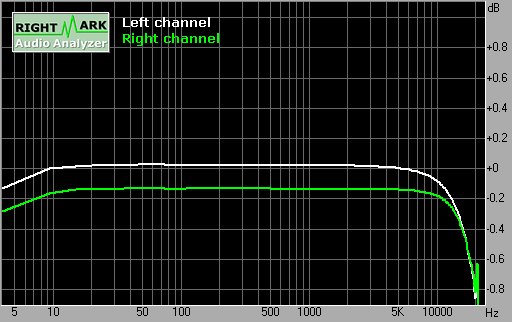
Here is a vertical zoom on my CD Player's frequency response, seen from the analog input of a DAT deck (Yamaha CDX860 -> Sony DTC55ES) :

Standard.png


The level difference comes from the DAT stereo input volume setting. On one hand, the roll off is -1 dB at 20 kHz. On the other hand, the flatness from 20 to 2000 Hz is as accurate as 0.02 dB.

Last, for interconnects, I have measured a whole set of them, from the 2 € spaghetti to a 560 € pair of Tara Labs, with the same setting as above, and substracted the response from it, in order to show the difference between cables.

You can see all the results at the bottom of the account of our double blind test here : homecinema-fr.com &bull; Afficher le sujet - Résultats du test en aveugle - câbles de modulation

From the top graph to the bottom graph :
-The raw frequency response of the measurment setup, with cheapo interconnects (same as above).
-Difference with itself, measured again : shows the accuracy of the playback and recording process.
-Difference with itself, measured again after all the other measurments : shows the drift due to heating or other slow variations.
-Difference with an SB64 cheap soundcard output, just to show a standard frequency response.
-Difference between standard and ACR interconnects
-Difference between standard and Audioquest interconnects
-Difference between standard and DIY interconnects
-Difference between standard and DIY interconnects (unshielded)
-Difference between standard and RG179 coaxial cable
-Difference between standard and standard + 5 meters extension of standard interconnects
-Difference between standard and Tara Labs interconnects
-Zoom in the treble end of the raw frequency response of the measurment system.

Interpretation : the one pixel deviations can be assumed to be rounding errors in the measurment software. The high frequency peaks occur at a very low output level according to the raw frequency response, thus can be caused by differences in the background noise from cable to cable.

Thus the only significant deviation that can be associated with interconnects is the 0.02 dB roll off that occurs at 20 kHz when 5 meters of cheap extention cord is added behind the standard interconnects, which makes a total of 5+1 = 6 meters of standard cable, with a set of additional CINCH connectors in the middle.

Nota bene : contrary to a common belief, thin standard 2 or 3 euros interconnect are actually coaxial shielded pairs.
Nota bene : in french, interconnects are called "câbles de modulation".
 
Sep 9, 2008 at 7:59 PM Post #8 of 15
Sep 9, 2008 at 8:22 PM Post #9 of 15
Not reliably. We heard many bizarre things, but we often contradicted each other, sometimes insisted that balance or volume was accidentally changed by the operator, wich was not the case.
But we systematically messed up the cable identification, believing they were changed while they were not, or the opposite.
One of us even noticed an improvement when the 5 meters extention was secretly added by Patrice without telling us (others did not agree, or thought that it was the same).

So the test was a complete failure regarding interconnects identification.

It was nonetheless interesting because we heard many things that were not there, and also because it was on a high end system.
 
Sep 18, 2008 at 4:28 AM Post #11 of 15
Quote:

Originally Posted by Happy Camper /img/forum/go_quote.gif
What is used for figures in the synergy formula? There has to be some general matching guidelines to start with.


It would actually be a fairly straightforward process. Somebody could measure the impulse response of all the components to get their transfer functions. You can then dump those transfer functions into a simple model to get the frequency response of the entire system.
The problem is logistical. It wouldn't make sense for manufacturers to publish transfer functions because you can't expect customers to have a systems engineering background to know what to do with the equations.
 
Sep 21, 2008 at 4:39 AM Post #14 of 15
Quote:

Originally Posted by digger945 /img/forum/go_quote.gif
I think from my own experiments with interconnects for the Is it possible to hear something that can't be measured. thread, it will take a fair amount of magnification to ever see the audible difference between high end systems.
What exactly do you mean, dgbiker, by "impulse response" and "simple model"?


When you hit a system (electrical, mechanical, fluid, etc.) with an impulse, the output that you measure from the system (assuming it is a linear/linearized system, otherwise it gets messy) is the "impulse response". The reason it is valuable is that a step or impulse theoretically contains every frequency, so the result you get is representative of all operating conditions.

What you get from the impulse response is a transfer function that describes the behavior of the part, relating the output to an input. Getting the transfer function can be pretty tough, but once you have it it only takes a fairly simple model to recreate your whole system. You can just multiply the transfer functions of all your components to get a whole system function. Do a frequency sweep on the input to that equation and you have the frequency response of your whole system- that will tell you how your components "synergize".
 

Users who are viewing this thread

Back
Top