arspy87
100+ Head-Fier
- Joined
- Jan 7, 2004
- Posts
- 329
- Likes
- 12
Hey everyone,
So after building myself a typical CMoy for my headphones, I decided to see how far I could push the CMoy technology. I had noticed that my small 9v amp was able to power bookshelf speakers reasonably well, so... I built a 30v CMoy.
The circuit is pretty much the same except I used 1000uF capacitors, a 30v wall power supply, and some larger resistors for the +/- voltage divider. Op amps were OPA134s. Additionally, I added an output switch to alternate between 1/8" output to my computer speakers and RCA outputs to my roommate's stereo. I mounted it in a plastic enclosure I got at Radioshack that's about 2x2x5 in.
Pics:
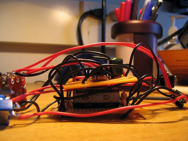
Innards... power circuit is on the bottom; amplification circuit is on the PCB above that.
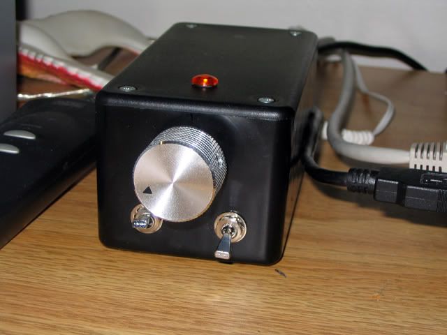
Front - two switches (power, output) and volume knob.
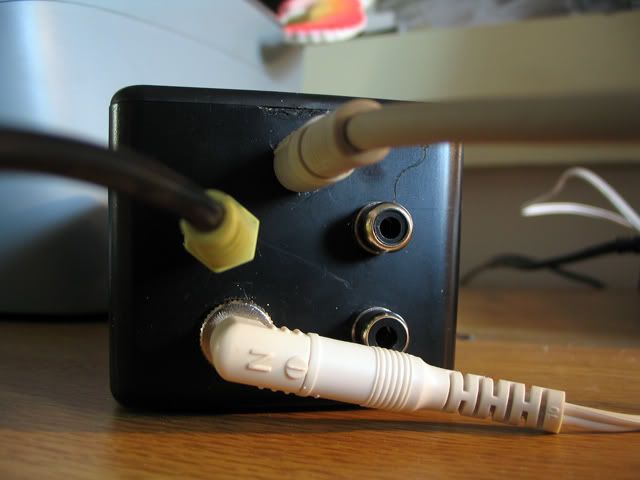
Back, with power, inputs, and outputs.
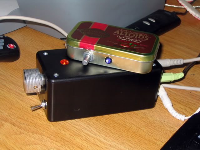
Picture with little brother CMoy =)
(The volume knob didn't fit as well as I wanted; I have to trim the potentiometer which I plan to do later on.)
Comments welcome!
So after building myself a typical CMoy for my headphones, I decided to see how far I could push the CMoy technology. I had noticed that my small 9v amp was able to power bookshelf speakers reasonably well, so... I built a 30v CMoy.
The circuit is pretty much the same except I used 1000uF capacitors, a 30v wall power supply, and some larger resistors for the +/- voltage divider. Op amps were OPA134s. Additionally, I added an output switch to alternate between 1/8" output to my computer speakers and RCA outputs to my roommate's stereo. I mounted it in a plastic enclosure I got at Radioshack that's about 2x2x5 in.
Pics:
Innards... power circuit is on the bottom; amplification circuit is on the PCB above that.
Front - two switches (power, output) and volume knob.
Back, with power, inputs, and outputs.
Picture with little brother CMoy =)
(The volume knob didn't fit as well as I wanted; I have to trim the potentiometer which I plan to do later on.)
Comments welcome!

