Strip Board CMOY Revisited
Aug 29, 2010 at 9:32 PM Post #76 of 107


Quote:
Why not just use the layout at the beginning of this thread, it works fine
smile_phones.gif

 
cheers
FRED


I was trying to get fancy and make it as small as possible :)  Big mistake LMAO
 
Just so I understand your layout, the third row up is your vground?  Is this right?
 
 
Aug 29, 2010 at 10:41 PM Post #77 of 107
Yes that's the VG, its using the 2 resistors as a voltage divider
 
How small do you want??


Thats the smallest I got to
bigsmile_face.gif


cheers
FRED
 
Aug 30, 2010 at 12:07 AM Post #78 of 107

Nice.
 
I dont need quite that small.  I want to fit it into an eclipse mints tin.  It will be plugpack powered (I have an 18v brick from an old laptop here).
 
I can make my layout a little bigger and still fit, but I was hoping to make it as compact as possible!  A bit more playing I think!


Quote:
Yes that's the VG, its using the 2 resistors as a voltage divider
 
How small do you want??


Thats the smallest I got to
bigsmile_face.gif


cheers
FRED


Aug 30, 2010 at 10:20 AM Post #80 of 107
Thats a lot better, but there is still one mistake.
Your input/feedback resistors on the left side
are connected to V- instead of Ground.
 
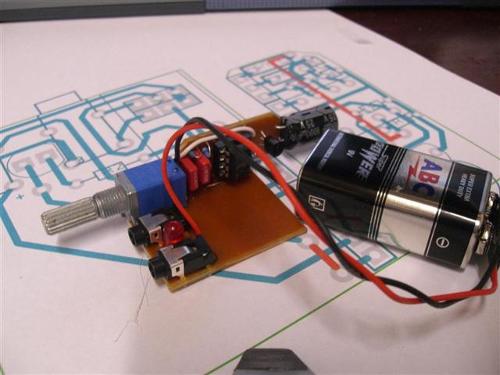
Here is a picture of the one I did last year.
It's not quite as small as the one you are
trying to do, but it's close...


Aug 30, 2010 at 6:59 PM Post #81 of 107


Quote:
Thats a lot better, but there is still one mistake.
Your input/feedback resistors on the left side
are connected to V- instead of Ground.
 
Here is a picture of the one I did last year.
It's not quite as small as the one you are
trying to do, but it's close...


Thank you!  Now you have pointed that out I can see it plain as day. (took me about 15 minutes of staring at it to figure out what I had done though! :) )
 
Once I fix that I should be good to go right?
 
Aug 31, 2010 at 6:51 PM Post #83 of 107
ok, I got it built last night.  No pics yet sorry....
 
It works!  Igiven the size of the PCB, and the locations of the connection points for the sockets and so forth, I cant fit it in the tin I want.  I'll be doing another one with a slightly longer board, this way I can hopefully reduce some of the air wiring!
 
Thanks guys for all of your help troubleshooting my circuit
 
Sep 4, 2010 at 2:49 AM Post #86 of 107
This is my efforts with an eclipse tin Cmoy
 
A while ago now, its very tight in the tin and this was the only way I could get it to fit :)


I'm fairly sure I still have the layouts and you more than welcome to them, you'll just need to learn toner transfer :)
 
cheers
FRED
 
Sep 4, 2010 at 7:42 AM Post #90 of 107
Sorry mate :)
 
things like that are just done for the challenge of doing it, there's only the one
 
why not have a crack yourself?
 
I'll share anything that might help
 
cheers
FRED
 

Users who are viewing this thread

Back
Top