Strip Board CMOY Revisited
Mar 7, 2010 at 12:39 AM Post #61 of 107
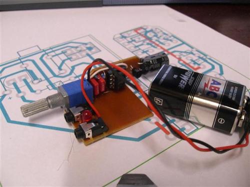
I saw this thread back on top today and decided to build a quickie. Never as easy as you think...with all the parts I have, I don't have 2 of the resistor values, and I have no opamps. I was excited to see that I could get 3 of these amps built out of a single $0.89 perf board (making it a strip board with resistor leads on the back).
I'll put some of those resistors and some different opamps on my next order, just to finish the 3 boards I cut out of the perf board. They should make nice little gifts for a few friends.
 
Mar 7, 2010 at 4:04 AM Post #62 of 107
Don't get too hung up on the exact resistor values - a step or two either side is probably going to be fine, just so long as you make the left and right channels identical.

Particularly the gain-setting resistors - who cares if you don't have a gain of 11? That will depend on your headphones and source anyway.
 
Aug 29, 2010 at 7:45 PM Post #63 of 107
Hi
 
I am looking to build my first cmoy.  I am wanting it to be as small as possible, as I want to put it in an Eclipse mints tin.
 
Can somebody please look at my stripboard layout I have created and tell me if I have made any glaring mistakes?
 
I'm using a tle2426 to get my dual supply.  I know I dont have the cap shown for the CNR pin on the TLE2426, can someone recomend a value?
 
cmoy.gif

 
Aug 29, 2010 at 8:30 PM Post #64 of 107
The data sheet recommends 1uF for CNR, but any value above that should work equally as well or better.
Also, your gain is pretty high...you might want to consider lowering R4/R4 to 5K.
I hope you know that C1 is going to be a round can and not a small disc, you might
want to make more room for it.
 
Aug 29, 2010 at 8:35 PM Post #65 of 107
Hi,
 
Thanks for the reply, yes fully aware that is c1 is a can style, I'll be laying it flat when it's soldered.
 
I'll take your suggestion on R4, and I'll buy both types.
 
Other than that, does my circuit look ok?
 
Aug 29, 2010 at 8:43 PM Post #67 of 107
The op-amp V+ and V- do not appear to be connected to anything.
I'm guessing that the red squares mean the strip board is cut at that
spot.
 
Aug 29, 2010 at 8:50 PM Post #69 of 107


Quote:
The op-amp V+ and V- do not appear to be connected to anything.
I'm guessing that the red squares mean the strip board is cut at that
spot.


Thanks,  I'll check that.  Yes the red squares are cuts.  The V- is connected via the link under the socket, I'll have to check the pinout of the chips again, and check for v+, but I thought I had connected it.
 
I think I just made a typo when I wrote in the value, you are correct on C1
 
Aug 29, 2010 at 8:52 PM Post #70 of 107
The combination of high gain with a low value pot is going to make it
pretty loud even when the volume is turned right down. You should
use at least a 20K pot and 200K for R2. A value of .1uF for C2 is kind of
low, I would recommend 1uF to get the best bass response.
Which op-amp are you using?
 
Aug 29, 2010 at 9:01 PM Post #72 of 107


Quote:
The combination of high gain with a low value pot is going to make it
pretty loud even when the volume is turned right down. You should
use at least a 20K pot and 200K for R2. A value of .1uF for C2 is kind of
low, I would recommend 1uF to get the best bass response.
Which op-amp are you using?


I will be using an OPA2132.
 
You were right with the v+ line.  I'll add a jumper for that somewhere. 
 
Those values were just the ones off the tangent recomendations.  I'll post up my parts list shortly
 
Aug 29, 2010 at 9:04 PM Post #73 of 107
I'm sorry to sound so negative...
But the more I look, the more things I find wrong...
Please don't get discouraged.
It's all a great learning experience!
 
V- Should be connected to Battery -, not TLE out.
 
You might want to just start again and double check that
you know where everything is supposed to go...
 
Aug 29, 2010 at 9:22 PM Post #74 of 107


Quote:
I'm sorry to sound so negative...
But the more I look, the more things I find wrong...
Please don't get discouraged.
It's all a great learning experience!
 
V- Should be connected to Battery -, not TLE out.
 
You might want to just start again and double check that
you know where everything is supposed to go...


Thanks, Not discouraged at all, learning is the name of the game here!
 
Can I ask what is wrong with the feedback loop? 
 
Aug 29, 2010 at 9:23 PM Post #75 of 107
Why not just use the layout at the beginning of this thread, it works fine
smile_phones.gif

 
cheers
FRED
 

Users who are viewing this thread

Back
Top