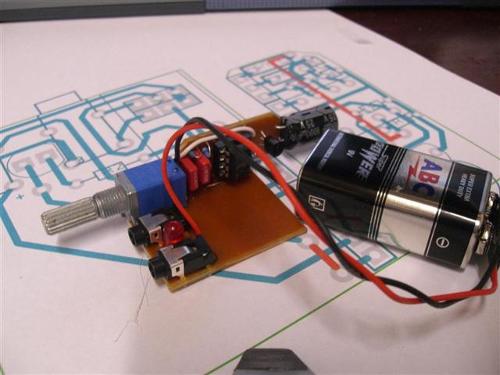
Strip Board CMOY Revisited
Dec 16, 2009 at 5:52 AM Post #16 of 107
OK maybe a trace of sarcasm
very_evil_smiley.gif


just having a bit of fun

the thruth is freezing the strip board in the freezer made no difference - and I had such high hopes
frown.gif


Oh well back to fitting a B22 into an Altoids tin

cheers
FRED
 
Dec 16, 2009 at 6:18 AM Post #18 of 107
Yes it was brilliant, nice to see an amp that cost more than the case
smily_headphones1.gif
 
Dec 16, 2009 at 11:22 PM Post #20 of 107
Hi Billy

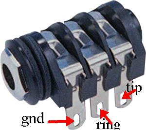
Gnd goes to gnd
ring is right goes to pin 7 of the chip
Tip is left goes to pin 1 of the chip

ignore the other three pins they are switchable

cheers
FRED
 
Dec 17, 2009 at 4:59 AM Post #21 of 107
Quote:

Originally Posted by Billy213 /img/forum/go_quote.gif
Fred would you be able to do me a diagram to show how I would connect up my 6 pin 1/4 headphone output jack? I'm really struggling to find out how it should be connected.

1/4†Stereo Socket with Chrome Bezel : 6.35mm (1/4 Inch) Stereo Jacks : Maplin

That's what I have. The rest of my layout matches yours. I hope I've got my pot wiring right, only time will tell. :p


i really like how tanget recommends toning them, then any plug u ecounter will be easy.....just plug up a male to male interconnect cable to jack. in yourcase an adapter to the 3.5mm might make things easier, since ive never seen a 1/4 male to male....anywho then touch the different parts of the male tip....ground,right chanel, left channel(right) with a multi-meter to the tips of the jack connection to figure out which goes where in your circuit.
 
Dec 20, 2009 at 11:46 PM Post #23 of 107
Jaycars are fine they don't have pots with switches so seperate pot and switch


CAT. NO. ZL3972 OPA2134 opamp (its all they have)
CAT. NO. RP8756 10K Log double gange pot
CAT. NO. RM7165 0.47uF 100V MKT capacitor (2)
CAT. NO. PS0132 3.5mm skt (2) better for air wireing
CAT. NO. RE6314 470uF low esr 16Volt (2)
CAT. NO. PH9233 battery clip
CAT. NO. ZD0150 red led
CAT. NO. ST0335 toggle switch
CAT. NO. PI6452 8pin IC socket


metal film resistors 1/2watt

10K (2)
1K (2)
100k (2)
4.7K (2)
6.8K for led

chunk of strip board and some solder (60/40)


Hope that helps
cheers
FRED
 
Dec 21, 2009 at 10:25 PM Post #24 of 107
Fred I've completed mine but it's not working properly. I've got sound from the right channel and a very faint sound from the left. It also distorts when I turn up the volume. Any ideas?
 
Dec 22, 2009 at 12:06 AM Post #25 of 107
Yes its broken
very_evil_smiley.gif


Sorry couldn't resist
smily_headphones1.gif


The circuit works so you've proberbly made a simple mistake its easy to do, any chance of a picture or two

cheers
FRED
 
Dec 22, 2009 at 1:37 PM Post #26 of 107
Yeah I'll upload a couple when I get home from work tonight. Gonna 'borrow' their soldering iron for a while as well. A rather hot 120W 110v one, works rather nicely.

Only problem with mine is the wire I've used, can get in the way a bit.. Oh, and it doesnt have an on/off switch.
wink.gif
 
Dec 23, 2009 at 12:59 AM Post #28 of 107
Get a old toothbrush or similar, dip it in meths and scrube the bottom of the board blot it up with a tissue. then have a good look for shorts between the traces
 
Dec 24, 2009 at 6:41 AM Post #29 of 107
Just thought , how is the input connected to the pot, its hidden in the pics
 
Dec 26, 2009 at 8:55 PM Post #30 of 107
I spent some time working on a strip board cmoy, the input caps are off the board and it uses some TLE chip for rail splitting (tangentsoft). You can really make a compact cmoy with stripboard.

3_800x532.jpg


15_800x532.jpg
 

Users who are viewing this thread

Back
Top