Stax SRM-T1 Repair, Re-Cap, Mod
Jan 24, 2016 at 10:06 PM Thread Starter Post #1 of 90

spaceace1014

100+ Head-Fier
Joined
Jan 17, 2013
Posts
153
Likes
25
Alright so I just bought Tus-Chan’s version “B” SRM-T1. It reportedly has a dead right channel which just sounds like fun to me. So time for a little background and then the plan. I got into electrostats about 3 years ago and I’ve had three main amplifiers in that time. The SRM-1/MK2, SRM-717, and the SRM-727. With help from Spritzer, Kevin Gilmore and other head-fiers I’ve worked on all of them. With the exception of spritzer’s feedback mod for the 727 which has been written about and photographed to death I’ve tried both for my sake(Since I am no expert) and the sake of those who will come later to document in as much detail as possible what I’ve done and what I’ve used to do it. I plan for this thread to follow in the same vein.
 
So here’s the plan:
1.Figure out why the right channel is dead and fix it.
2.Pull out all of the electrolytics and replace them with good well made new manufacture caps.
3.Apply and very carefully document any popular mods that you guys think will make a difference one at a time. I hear rewiring to ECC99 is a good one. I’m open to suggestions here.
4.When all's said and done compare the feedback modified 727 to the fixed and modified T1.
 
To be continued when the amp arrives! 
 
Feb 3, 2016 at 2:23 AM Post #2 of 90
The amp has arrived! 
 
It is not actually broken. The Lambdas on the other hand seem to have a failed channel. So It's time to skip to segment two of the plan. Re-cap! 

There are 10 electrolytic capacitors contained within the amp. Judging by the size and values of the main PSU caps these are completely original and therefore very old.
 
Original Caps(Sizes are as close as I could measure):
 
1.C11-C14
100uF 400V
30mm Diameter
60mm High
12.5mm Lead Spacing
 
2.C9,C10
10uF 50V
10mm Diameter
13mm High
6.5mm Lead Spacing 
 
3.C21-C24
220uF 10V
6.5mm Diameter
12mm High
3.5mm Lead Spacing


I tried to get high quality replacement caps with values and lead spacing's that were somewhat close to what the original capacitors had. For the small capacitors I wanted Panasonic FM and/or FC since they have both have solid reputations as audio capacitors and I looked to Panasonic for the large capacitors as well however mouser is showing everything in that range from them as end of life so I went with Nichicon since they also have a solid reputation. Side note: The small capacitors have radial leads. The large caps are snap in.     


Replacements:
 
1.C11-C14
Nichicon

LGR2G221MELA50

http://www.mouser.com/Search/ProductDetail.aspx?R=LGR2G221MELA50virtualkey64700000virtualkey647-LGR2G221MELA50
 
2.C9,C10
Panasonic

EEU-FC1H100LB

http://www.mouser.com/Search/ProductDetail.aspx?R=EEU-FC1H100LBvirtualkey66720000virtualkey667-EEU-FC1H100LB
 
3.C21-C24
Panasonic

EEU-FM1A221

http://www.mouser.com/Search/ProductDetail.aspx?R=EEU-FM1A221virtualkey66720000virtualkey667-EEU-FM1A221


Feb 3, 2016 at 2:39 AM Post #3 of 90
So for those who haven't done this before the basic capacitor replacement process is about as basic a procedure as it gets. I'm by no means an expert and it's easy for me so trust me if you've ever looked sideways at a soldering iron you'll be able to do it and you should do it. Based on my past experiences this should make a pretty significant difference in the sound.
 
0. Let the amp sit for an hour completely unplugged. This is more time that it needs to bleed off the power it's got in its capacitors but I can't stress enough that this is important. These Stax amps run at extremely high voltages and you might not live to regret skipping this step. When in doubt test with a meter if you've got one or just go watch TV. 
1. Desolder and remove the existing caps. 
2. Solder in the new caps. Bend the leads if you must(You'll probabbly have to). Use 60/40 Solder since that's supposedly what Stax uses. Make sure you get the polarity correct. Do not reverse the polarity Scotty. Don't worry its marked. 
3. Re-bias the amplifier. 
4. Enjoy.
 
Ok re-biasing. This is also simple. You'll need a small flat head screwdriver and a volt meter. Take a look at this thread. It's for the SRM-1MK2 but it's the same thing.  
http://www.head-fi.org/t/648596/stax-srm-1-mk2-re-cap/15
 
Feb 3, 2016 at 2:50 AM Post #5 of 90
Ok, So I'm starting to research the ECC99 Mod while I wait for the capacitors.
 
Reference 1. Some photos of an amp that sold a while back. 
http://www.head-fi.org/t/688983/stax-srm-t1-ecc99-modified-240v
 
Reference 2. Photos of the bottom as well as some discussion of the mod. 
http://www.head-fi.org/t/223263/the-stax-thread-new/21000
 
Reference 3. More discussions and photos. 
http://www.head-fi.org/t/223263/the-stax-thread-new/17310
 
 
I found some information Spritzer posted on another forum which had enough information in it to reproduce the mod. These are his photos. (Thanks Spritzer... again)


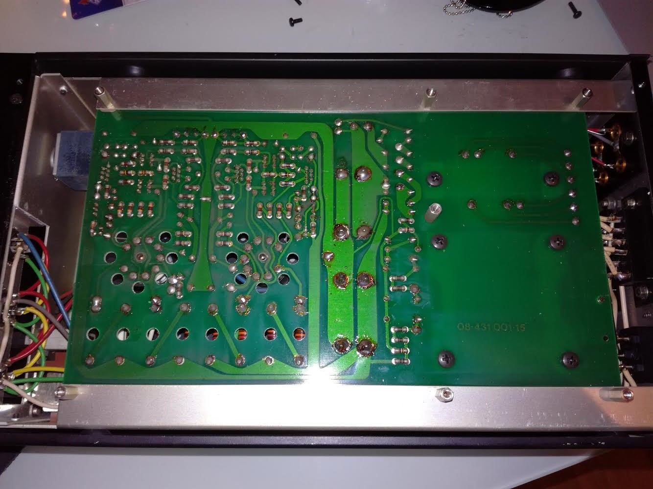
Bottom Side:
"Easy enough to accomplish, cut two traces, add two wires and bridge two pins on the sockets." - Spritzer


Top Side:
"On the top side all the anode resistors have to be changed for 30K/2W units. Rebias and you are done." - Spritzer

 
Feb 3, 2016 at 4:05 AM Post #6 of 90
Parts list for the mod: 
 
1. 8x Koa Speer, 2w, 30k ohm, metal film resistors. 
http://www.mouser.com/ProductDetail/KOA-Speer/MO2CT631R303J/?qs=sGAEpiMZZMtlubZbdhIBIENplELlLg1fQww4HanPscI%3d
 
2. 2x JJ ECC99 Tubes.
https://www.tubedepot.com/products/jj-ecc99-rf-double-triode-preamp-vacuum-tube
 
3. Some wire.
 
4. 60/40 solder.
 
Feb 3, 2016 at 4:31 AM Post #8 of 90
Ok, So as you can see above I've got a couple things in the works for this amp at this point but while FedEx takes its sweet time it's time to plan out the next phase and I've got a couple options. Here are some possible directions I can go. 
 
1.Swap out the input RCA jacks for new ones that aren't oxidized. 
 
2.Figure out how spritzer wired this SRM-1/MK2 for balanced input and implement it on the T1(Then somehow try to mod my metrum musette for balanced output)
http://www.head-fi.org/t/532723/fs-stax-srm-1-mk2-pp-fully-rebuilt-and-fitted-with-balanced-inputs 
http://www.head-fi.org/t/786236/stax-sr-407-balanced-srm-1-mk2-pp-modded-by-spritzer-price-reduced
 
3.It looks like a lot of the T1's that have been worked on have had their wiring updated. So Update the wiring. 
 
4.Go insane and build a KGSSHV power supply in an external box then somehow wire it through an umbilical to the T1
 
5.Swap the alps volume control for something better like a stepped attenuator. Not an RK50.
 
Aug 30, 2016 at 8:38 PM Post #11 of 90
Hi spaceace1014,
                            I seem to have stumbled onto the path you've already trodden. I just discovered Stax and I currently have a SRM1 mk2 and a T1W just arrived. The T1W sounds really bad compared. I can't afford to keep both so I was wondering how your ECC99 mod went? Also did you suss how to do the Spritzer balanced input conversion on your SRM1 mk2 ? 
Thanks for the T1 tread I think I can do it OK but how does it sound compared to the stock one?
 
Cheers
Neil
 
Jan 15, 2017 at 11:07 PM Post #13 of 90
I know this thread is old but In response to those who've asked. using it with my Metrum Musette and my SR-507's I found it to be the finest listening experience I've had to date. I preferred it strongly to my Spritzer mod 727. 
 
Apr 11, 2017 at 7:38 AM Post #14 of 90
Hi, sorry for reviving this topic. I ordered the stuff mentioned before this great thread but stumbled on after opening mine that i have a "older" T1 version.
The top side looks like this one D3S_5330-inside-1600.jpg
and the bottom side looks like
9934458.jpg


So im wondering if the EC99 mod does work with this version? So how do i rewire this bad boy to accept EC99?
 

Attachments

  • srm t1 pcb.jpg
    srm t1 pcb.jpg
    240.5 KB · Views: 0
  • IMG_3593.JPG
    IMG_3593.JPG
    3.6 MB · Views: 0
  • IMG_3594.JPG
    IMG_3594.JPG
    3.4 MB · Views: 0
  • IMG_3595.JPG
    IMG_3595.JPG
    3.2 MB · Views: 0
  • IMG_3597.JPG
    IMG_3597.JPG
    3.3 MB · Views: 0
  • IMG_3598.JPG
    IMG_3598.JPG
    3.3 MB · Views: 0
  • IMG_3605.JPG
    IMG_3605.JPG
    4.6 MB · Views: 0
Last edited:
May 21, 2017 at 1:03 PM Post #15 of 90
Well after messaging with Spritzer he actually suggested me to use 6N6pi tubes instead of modify the existing to take Ec99. I Also did the recapping, what im going to do after is to upgrade the wiring and propably change the RCA's.

But for now it seems to work just fine, im gonna let the tubes burn in so can't comment on the sound quality.

So this is what spritzer said to me about the tubes. (hopefully u won't mind me posting, thank you Spritzer)
Spritzer
Yeah, the 6n6pi uses the same pinout so you can leave the socket alone. The problem though is that they use a lot more heater current, about 930mA compared to 600ma for the 6CG7.

Yup, you should change the anode resistors to 30K/2W units or greater thermal dissipation.

http://www.tubes.ru/techinfo/HiFiAudio/6n6p.html
 

Users who are viewing this thread

Back
Top