Starving Student PCB's
Nov 23, 2013 at 6:37 AM Post #121 of 392
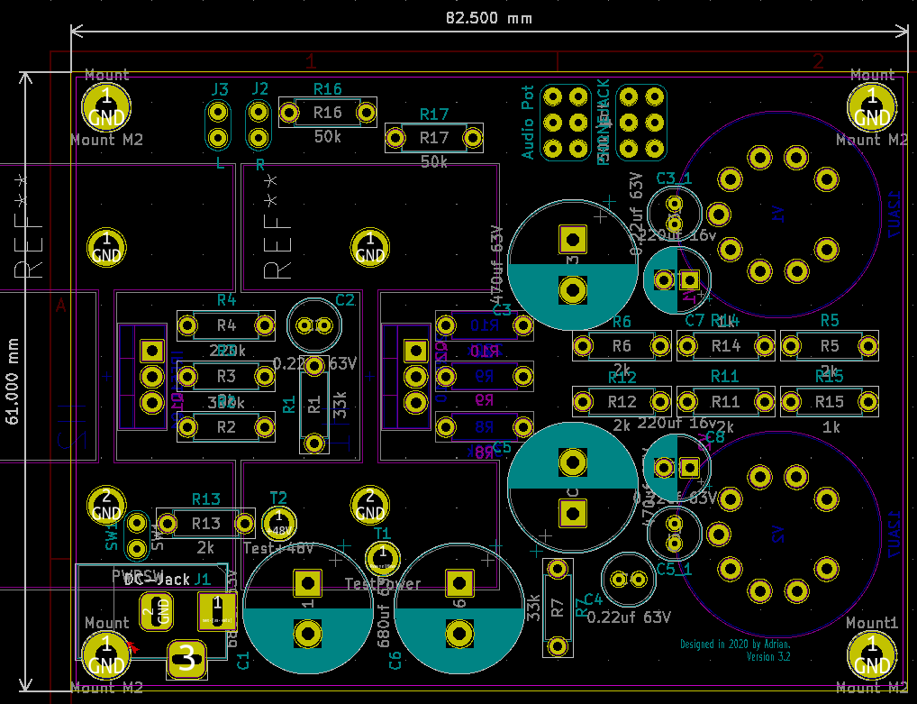
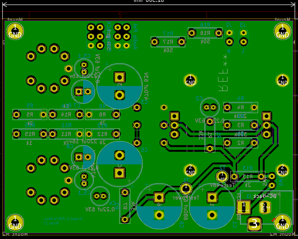
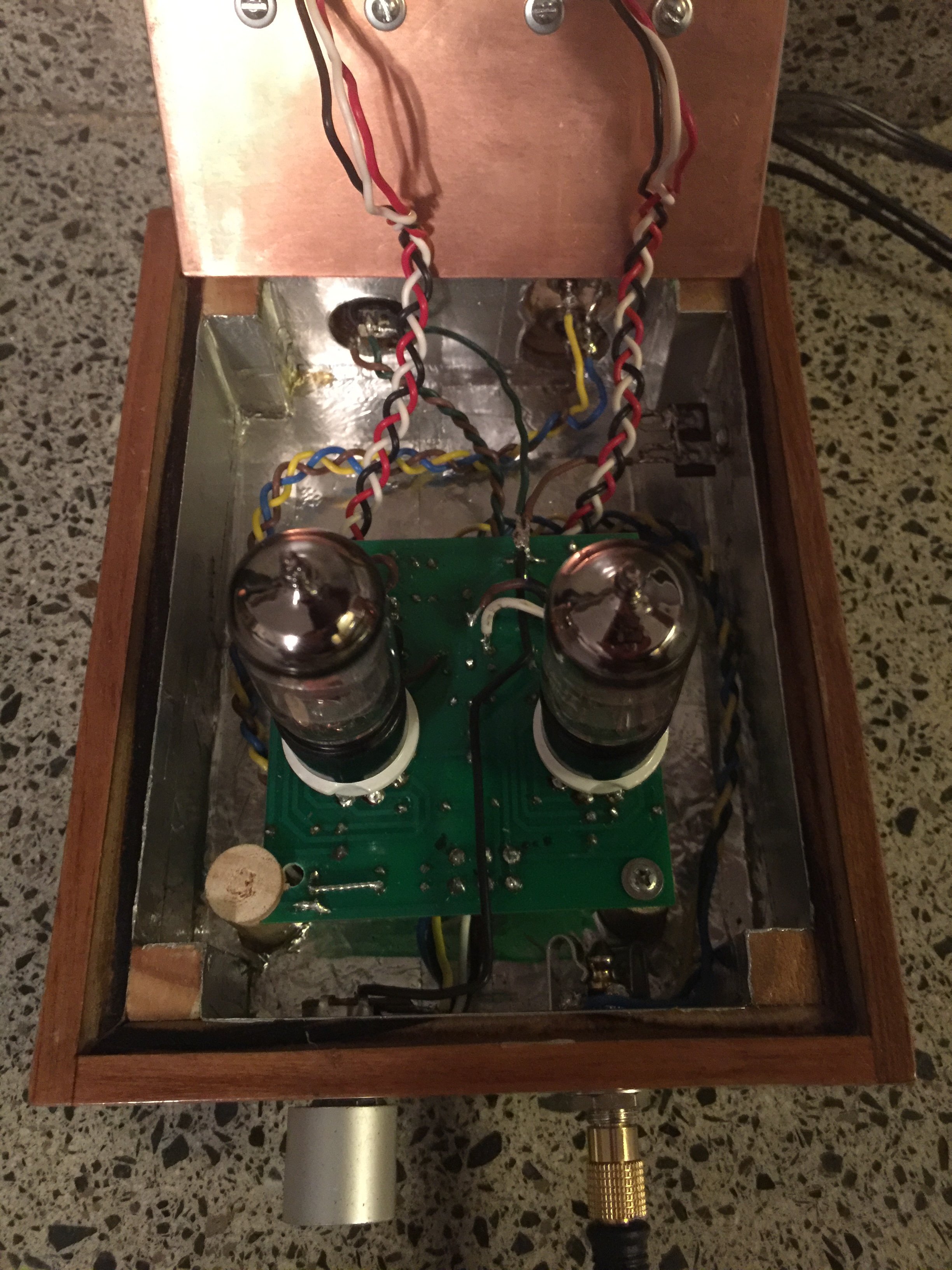
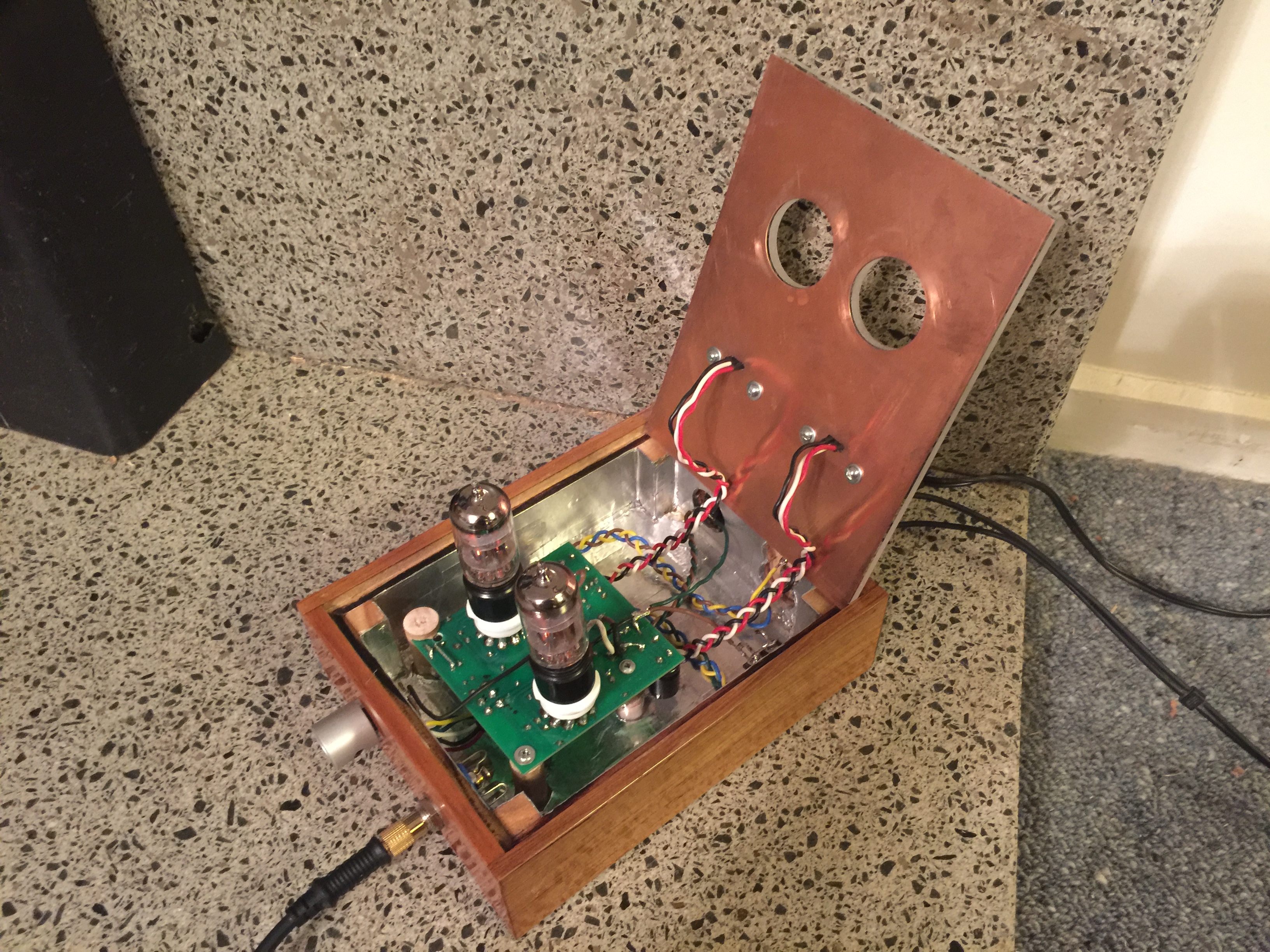
Any chance of better pictures of both sides of the board?
 
its hard to see how you've wired it up
 
cheers
FRED
 
Nov 23, 2013 at 12:45 PM Post #123 of 392
@RealSpark
 
In my boards one of the little squares that should indicate ground was wrong, I don't remember now which one it was, input or output, but if you trace the signals on the pcb you can see the mistake.
 
Looking at the pictures in the first page I think it was the input ground pad. It's actually the one facing the edge of the pcb instead of the one on the silkscreen.
 
Nov 23, 2013 at 10:42 PM Post #124 of 392
  Wow, I love the idea of using a Mac Mini case as the housing on that. So pretty. How much did the whole setup set you back? And where would you pick up the housing like that, just had one lying around?

I bought all of the parts from China in one shipment. The Mac Mini case is 90 RMB, boy that is authentic mac mini case. I thought it is a fake one initially. The tubes are cost is 28 RMB each, free matching service. I bought one pair plus one for my other 12AU7 amp. A brand new 48V 2A power supply only for 20 RMB. Capacitor, resistors and all the other components cost about 80 RMB in total. Shipment to Singapore is about 40 RMB, only took 3 days and I got them. So in total it is about 60 SGD or 50 USD.  
 
Nov 23, 2013 at 10:42 PM Post #125 of 392
  @RealSpark
 
In my boards one of the little squares that should indicate ground was wrong, I don't remember now which one it was, input or output, but if you trace the signals on the pcb you can see the mistake.
 
Looking at the pictures in the first page I think it was the input ground pad. It's actually the one facing the edge of the pcb instead of the one on the silkscreen.

You are right! My output is wrong. I soldered one channel to ground. Now its working totally fine! Cheers mate!
 
Dec 8, 2013 at 9:56 PM Post #129 of 392
There are no mounting holes. How have you guys mounted it on the chassis.
The only thing i see is the pot that can be mounted, but is that mounting strong enough to hold the pcb and the tubes. I was actually thinking of ditching the pot, but looks like i might need it... Any issues with a 100k pot. I plan to use this with 32 ohm headphones.
Any particular reason why i see most of the people mounting the tube sockets on the other side.
 
Dec 8, 2013 at 11:45 PM Post #130 of 392
There is plenty of room to drill mounting holes through the board, depending on the enclosure you are planning to use
 
I have used a 100K pot it seemed to work fine
 
the board was designed to have the tubes on the track side, if you put them on the other side all the connections will be mirrored - so not going to work :)
 
cheers
FRED
 
Dec 9, 2013 at 4:27 PM Post #131 of 392
I've seen a few calls/references to a BOM or parts list and having done the homework (and hopefully gotten it right:)  I created a 12AU7 PCB based list for Mouser.  The link is read only but if you see errors there, please let me know and I'll update so future finders of the thread don't have to recreate as it's very easy to make mistakes. In addition to this list, you'll need materials for a case and a 9 pin ceramic tube socket- I got some of the 9mm high ones off ebay and of course a couple of tubes and a power supply.
 
Dec 10, 2013 at 7:09 AM Post #133 of 392
I doubt that it will make any difference in reality. But if you have them around and the voltage rating is sufficient why not use them :)
 
cheers
FRED
 
Dec 12, 2013 at 6:57 AM Post #135 of 392

Users who are viewing this thread

Back
Top