victory
New Head-Fier
- Joined
- Apr 15, 2017
- Posts
- 4
- Likes
- 10
Good morning,all
Recently I am researching ICL8038 audio oscillator. I found a circuit diagram that given above shows a variable audio frequency oscillator using ICL8038. According to its information, this circuit is very useful while testing audio related projects and the frequency range of this circuit is 20Hz to 20KHZ. POT R6 can be used for adjusting the frequency while POT R9 can be used for adjusting the distortion. POT R4 can be used for adjusting the duty cycle while POT R7 can be used for nullifying the variations in duty cycle. C2 is the external timing capacitor and R5 is a pull up resistor. You can see them from the following circuit diagram.
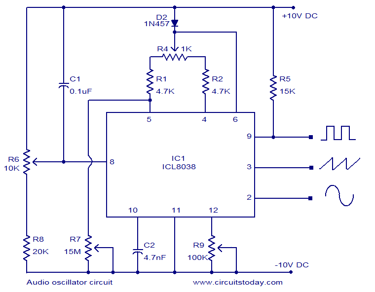
Now the problems I have 3 at least:
1). I assume the supply is +10V-0V-10V, but where then is the 0V connected?
2). what forms the output of the circuit, I see the +ve sides are formed from the outputs of the IC on either pins2,3 & 9 of IC1, and what forms the -ve output?
3). I appears that pin 9 of IC1 is connected via a 15K resistor to the +10v line, are there similar connections to pins 2 & 3?
How to explain it? Can you?
Best wishes~
Recently I am researching ICL8038 audio oscillator. I found a circuit diagram that given above shows a variable audio frequency oscillator using ICL8038. According to its information, this circuit is very useful while testing audio related projects and the frequency range of this circuit is 20Hz to 20KHZ. POT R6 can be used for adjusting the frequency while POT R9 can be used for adjusting the distortion. POT R4 can be used for adjusting the duty cycle while POT R7 can be used for nullifying the variations in duty cycle. C2 is the external timing capacitor and R5 is a pull up resistor. You can see them from the following circuit diagram.
Now the problems I have 3 at least:
1). I assume the supply is +10V-0V-10V, but where then is the 0V connected?
2). what forms the output of the circuit, I see the +ve sides are formed from the outputs of the IC on either pins2,3 & 9 of IC1, and what forms the -ve output?
3). I appears that pin 9 of IC1 is connected via a 15K resistor to the +10v line, are there similar connections to pins 2 & 3?
How to explain it? Can you?
Best wishes~
