


AK4499ex has current output not voltage like the others AKM chips.
You are using an out of date browser. It may not display this or other websites correctly.
You should upgrade or use an alternative browser.
You should upgrade or use an alternative browser.
SMSL D400EX & D400ES - Impressions Thread
- Thread starter XERO1
- Start date
It's all a matter of the right winding ratio.
PcChip
100+ Head-Fier
FYI, I've found that on the D400Ex , i2s input sounds *much* better than USB
I'm currently using a Matrix X SPDIF 3, but plan on getting a Holo Red soon
I'm currently using a Matrix X SPDIF 3, but plan on getting a Holo Red soon
AudioQuality777
100+ Head-Fier
- Joined
- Apr 11, 2016
- Posts
- 159
- Likes
- 121
FYI, I've found that on the D400Ex , i2s input sounds *much* better than USB
I'm currently using a Matrix X SPDIF 3, but plan on getting a Holo Red soonSMSL PO100 PRO
SMSL PO100 PRO also works well for i2s.
Last edited:
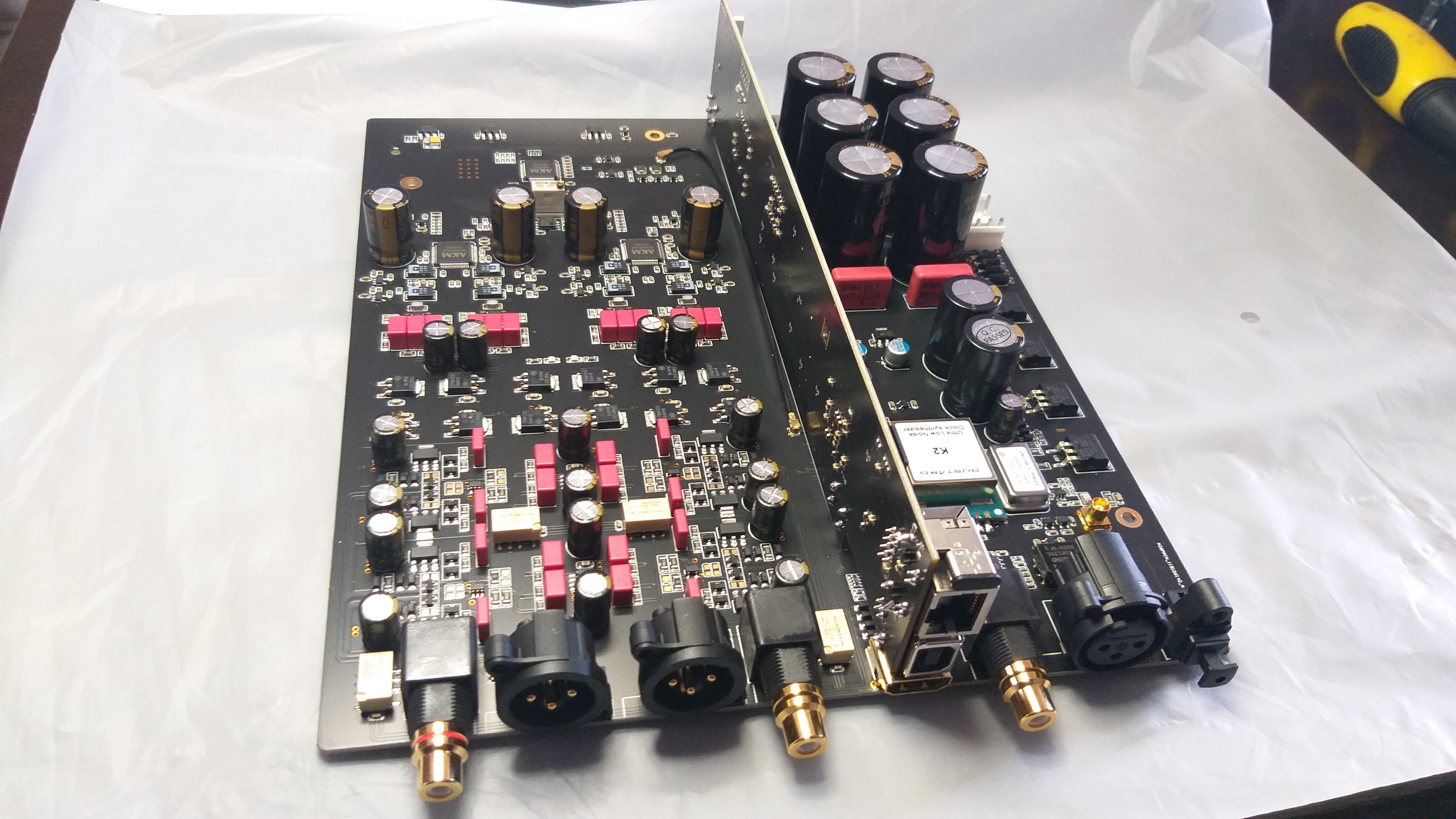
I spotted ugly electrolytic(!) coupling caps in the A26 in an otherwise nice-looking design. So, Gustard neither thought about trimming off the DC from the I/V stage.

Gustard A26 has not capacitors in a series with signal. That capacitors are at the output of the voltage regulators 78M12 and 79M12.
Nah, I don't think so. The traces from the red passive filters go right under the caps and come out on the other side. Also, the caps are located symmetrically to the filter stages, which makes no sense if they were connected to supply voltages further up. Look at the left channel. Why make a bend under the cap instead of going straight up?
Last edited:
JerryLeeds
500+ Head-Fier
- Joined
- Jun 12, 2015
- Posts
- 819
- Likes
- 199
Does anyone know the procedure to upgrade the firmware on the D400ES?
I found I recent version on … I hope they fixed the bad sound when the filter is turned off
Https://download.shenzhenaudio.com
I found I recent version on … I hope they fixed the bad sound when the filter is turned off
Https://download.shenzhenaudio.com
Last edited:
I see a "firmware upgrade software" and the firmware itself. My guess is that the former uploads the firmware to the device via USB. Installing a firmware without a proper installation guide is kinda risky, though.
AudioQuality777
100+ Head-Fier
- Joined
- Apr 11, 2016
- Posts
- 159
- Likes
- 121
SMSL forgot to put the installation guide in a file. ")
Nah, I don't think so. The traces from the red passive filters go right under the caps and come out on the other side. Also, the caps are located symmetrically to the filter stages, which makes no sense if they were connected to supply voltages further up. Look at the left channel. Why make a bend under the cap instead of going straight up?
I was open A26 and I measure all. A26 hasn't series capacitors.
Attachments
All that big smd "transistors look like" parts are voltage regulators, 78M12 and 79M12. All that 100uF Nichicon Gold capacitors are there for that voltage regulators.
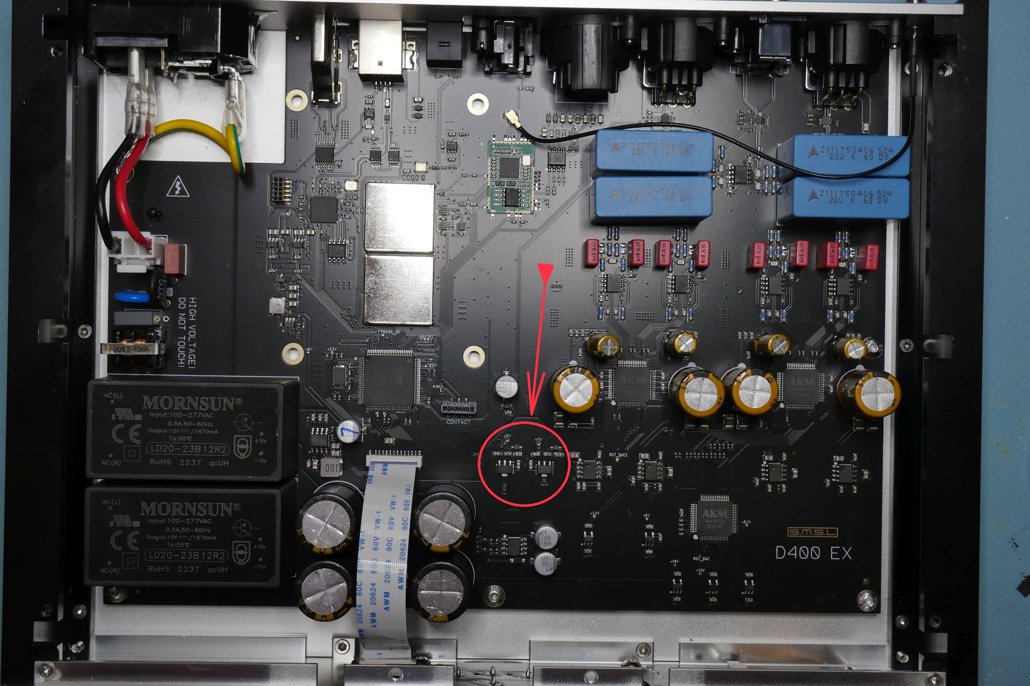
Measurements beat speculations And it's good news. So, this trim potentiometer has most likely something to do with offset trimming when there are no coupling caps. Can you explain where the traces go that come out under the caps in the direction of the passive filter stage? I reckon that the Nichicon UKW have a significant influence on the sound. I experimented with them once and they sound rather soft and dark. Thick lower midrange.
And it's good news. So, this trim potentiometer has most likely something to do with offset trimming when there are no coupling caps. Can you explain where the traces go that come out under the caps in the direction of the passive filter stage? I reckon that the Nichicon UKW have a significant influence on the sound. I experimented with them once and they sound rather soft and dark. Thick lower midrange.After I/V converter with opa1612, 4×opa1612, the signal go to the LPF. LPF are another two opa1612 again. Here is summing too. After that stage the signal is unballanced. After that, there is the output discrete buffer, four buffers. The signal here is again ballanced. Two of the buffer stages will invert the signal.
Measurements beat speculations
Ooohhhhhh.... I have an idea....Is better with series coupling capacitors instead of removing the 2.5v of DC ??? I say yes. Why ? With 2.5v at the output of the I/V op-amp converter, the op-amp will work in class A for 5v pp, or 1.77v rms. But we have + and - outputs, differential one, so, in fact we have 1,77v × 2 = 3.5v rms in class A regardless of the current !
That's the theory  . For the D400 I can tell for sure that the disadvantages of the coupling caps are bigger in terms of sound than the advantage of driving the OPAs better. The caps smear the treble.
. For the D400 I can tell for sure that the disadvantages of the coupling caps are bigger in terms of sound than the advantage of driving the OPAs better. The caps smear the treble.Users who are viewing this thread
Total: 3 (members: 0, guests: 3)
