small transportable Stax amplifier Modification thread
May 17, 2015 at 12:39 AM Thread Starter Post #1 of 44

AudioCats

Headphoneus Supremus
Joined
Feb 25, 2007
Posts
3,726
Likes
262
Location
CO, USA
Starting a thread about modifications on smaller Stax amps (SRM-X, X pro, Xh, 212, 252, etc).
 
*** warning: these amps have high voltage supplies inside. Before doing any work on the circuit board, always unplug the power and confirm HV rail voltage is at 0 (usually drops to 0 within a minute) .  
 
 
First up, some mods on a SRM-Xh (to drive a pair of 303, for work use)
 
The Xh board looks pretty simple, a lot less components comparing to the later models such as 212 and 252.


a) power supply section:
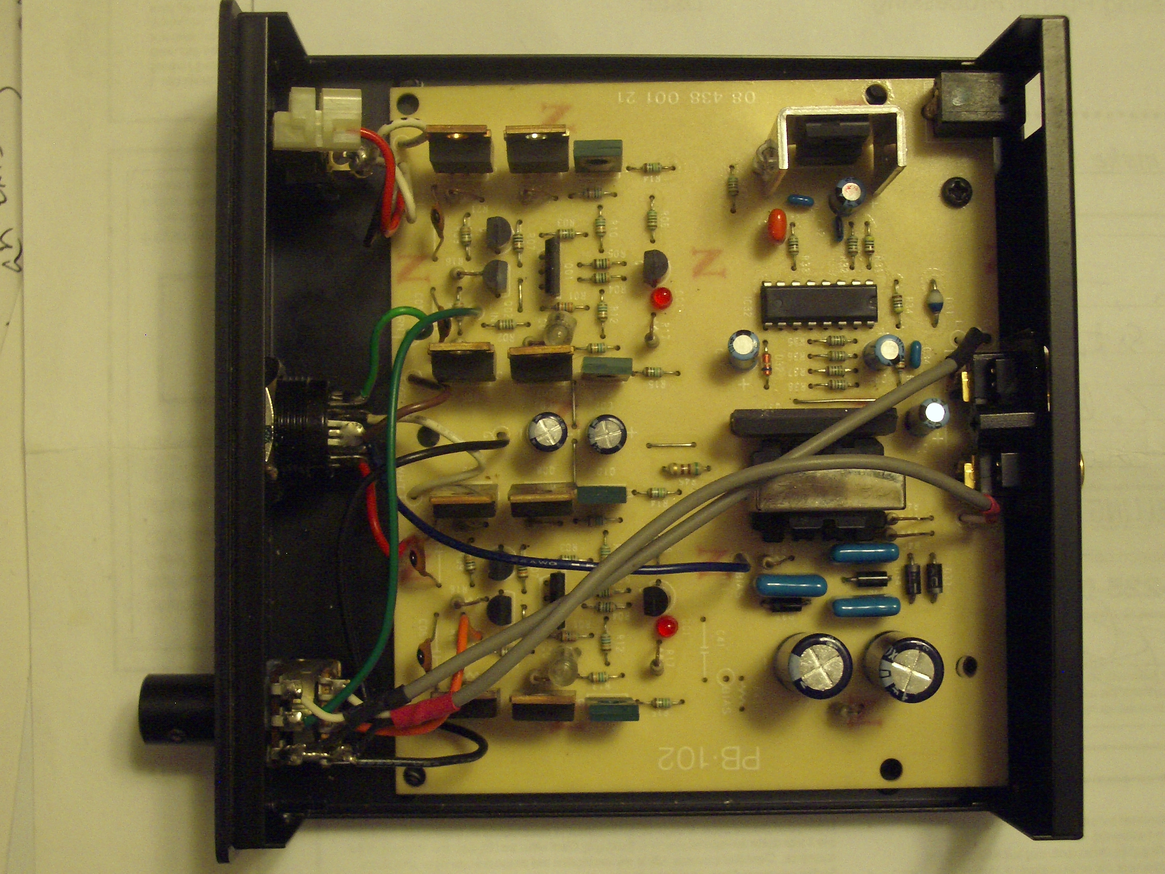
-- polarity protection: since this is intended for work use, there is a possibility of somebody, for whatever reason, plugging a wrong power plug into the amp. The Xh has an on-board voltage regulator (12v) to prevent over-voltage, it only needs an in-line diode for reverse polarity protection.  I added the diode right at the power switch. (desolder the out-most white wire and solder the diode to the switch terminal, then the white wire to the other end of the diode).
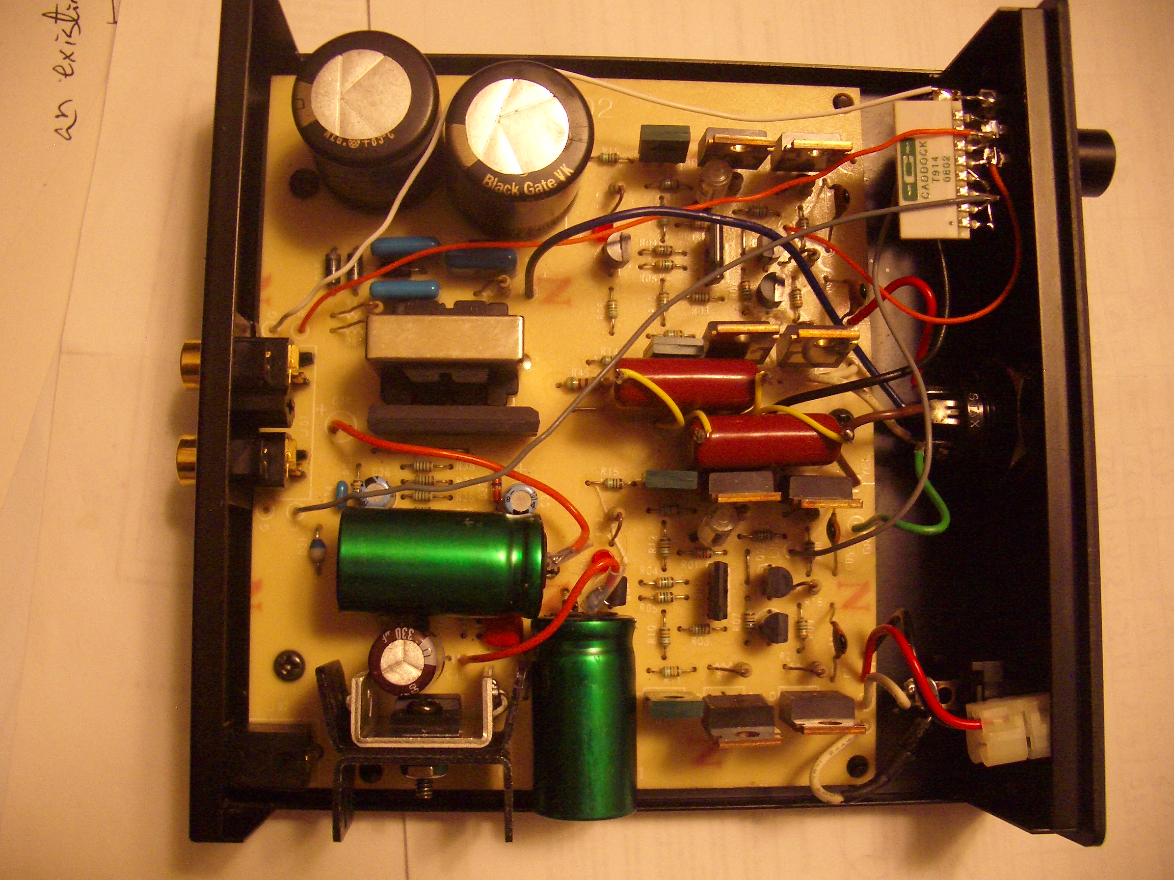
-- a 35v electrolytic is installed right after the diode as buffer. The one in the photo is a nichicon muse 2200uf/35v.
-- Extra heatsink fins are added to the existing heatsink to help the voltage regulator stay cool.
-- C35 is at the output pin of voltage regulator, it is changed to a  larger value one. Voltage rating needs to be at least 16v. I used a 330uf.
-- C38 is a buffer cap, after D31. Not sure what the intended purpose of D31 is, maybe to prevent damage to the step-up supply section in the case of a reversed polarity? Since I already have the in-line diode at the power switch, reverse polarity is no longer a concern.  I replaced c38 with a muse 2200uf (not direct replacement, had to add extra wire). D31 is short across, that increased the HV rail voltage from around +/-195v to +/-205v. 
-- speaking of HV rails, C39/40 are HV reservoir caps, stock value is 10uf/250v. The Xh is a very old model so it is prudent to replace these high voltage caps with fresh ones, and while you are at it might as well increase the capacitance value and use better parts. The size constrain here is mainly that the height has to be 1" or less. A quick search on digikey and mouser returned many suitable options for direct replacement, such as these low impedance nichicon and kemet.
(The ones shown in the photo below are blackgate VK 22uf/350v, they were the only right voltage caps I got, at the time of the mod,  that would possibly fit into this case.The VK seems to be working quite ok so I will probably just leave them in there.)
***!!! the exposed aluminum top might be "hot" depending on the cap's design (the VK's bare top measures 200v....and guess how I figure that out...."ZZZZZZZ! ouch! " ). I'd recommend adding insulation tape to cover it.
-- finally, c02 and c03 were replaced with larger value film caps (stock value is only 0.01uf).
 
May 17, 2015 at 12:40 AM Post #2 of 44
b) Amp section:
the Xh has direct DC coupled output so there is no output caps needing upgrade. And there is no adjustments to make. That leaves the only the signal input section to be modified. The stock volume control pot is a generic round 50k Alps, which is not bad, and there is not enough room to change it to a square Alps blue RK27, so I left it alone.

However there is still a lot that can be gained at the volume control section: convert it to shunt type (google "shunt volume control" if you are not already familiar with it). By doing so major sound quality improvement can be gained without any major change to the existing component. And we are talking about the kind of improvement from "good dynamic headphone" clarity to "good electrostatic" clarity.

When doing the shunt conversion you will need to add a pair of resistors in series, the quality of these resistors is of extreme importance, and yes you will hear the difference. Especially since we are using electrostatic gear, the differences come right out. It is not just the old carbon film vs metal film debate. One can easily tell the differences between AudioNote tantalum and Caddock TF020 film and Caddock Micronox film. (the vishay S102 is a little more subtle). What to use is kind of depending on personal preference, here are some of my notes:

* AudioNote Tantalum: warm and clear;good strong bass; voice a little recessed; very realistic voice, but....! it somehow give a hint of "gladness" to the voice, as if the singer has a little grin at the corner of his/her mouth when singing, the voice is always sweet, and even in a (supposedly) sad song it made me feel like the singer is not really mourning about her lost love, but instead just bragging about "look what I used to have"....Otherwise, great resistors.
*Caddock Tetrinox (ceramic chips): lay back sound, great clarity and texture, very high resolution, shows the performer's emotion really well (the best among all of the resistors I have tried). Great resistors to use, the only possible down side is that the clarity can sometime be too much, it can lead to slight "mid-range burn" (listening fatigue) depending on the rest of your gear.
*Caddock Micronox (Mk132, MP series): more closed in, warm and softer sound, good punchy bass. resolution not as good as the two above. Darker than the two above.
*Vishay metal foil (S102): somewhat a middle-ground among AudioNote and TF020 and micronox. More closed-in than TF020 but not so much as Micronox; resolution about the same as TF020 and AudioNote, but the sound is smooth smooth (without the "gladness" of AudioNote), possibly a little too smooth at times. If one consider Stevie Nick's voice is like "velvety sandpaper", the S102 will show more "velvet" while the TF020 will emphasize the "sandpaper" side a little more. This is a great resistor to start with, base on the result with s102 you will know which direction to further tweak the sound. It is very possible you would "like the sound so much might as well just leave it in there".

Now how about the more main stream metal film and carbon film stuff, like PRP and Takman? From my experiments, those are noticeably inferior when use as series resistor in a shunt volume control , the sound is either slightly dull (Takman) or has noticeable mid-range burn (prp), and the overall resolution is less than the top tier stuff above.

The result:
the sound is more clear and more enjoyable than a stock (but recapped) SRM-1/MK2. The stock SRM1MK2 has more horse power and stronger bass (quantity-wise) but the sound is not as refined as the modded Xh.
As of what % of SQ improvement is from which upgrade, I would say maybe 20% comes from the upgraded HV rail caps ( cleaner deeper bass become possible... other mods in the power supply section is just to improve reliability); the rest, 80%, comes from the shunt volume control convertion alone (again, premium series resistors must be used). So, I'd say if nothing else, one should at least do the shunt conversion, just add a pair of s102 in there and see how much more enjoyable the music gets.

photo shows the Xh still in testing stage so the wiring is a bit messy. All wires install in the mods have teflon insulation.
IMGP3020.jpg
 
Last edited:
May 17, 2015 at 12:40 AM Post #3 of 44
* SRM-212 modifications
 
my first encounter with the 212 was in the form of a SRS-005 (sr-003 baby stax + 212 amp combo) about 10 years ago. At the time I did not have other pro-biased phones so the only thing I used the 212 with was the baby stax. The result was disastrous, I could not handle the major "listening fatigue" from the combo, the sound was just too hard for my taste. (The baby stax is already mid-centric, I'd guess the 212 has a bit of mid-range burn of its own). I quickly sold the 005 and started playing with the more agreeable 001.
 
fast forward 10 years.... After getting (more or less) satisfactory results from the modded Xh, I started to wonder if maybe the 212 has more potentials to be exploited and can be tweaked to sound good with at least the lambda type phones. After all it is supposedly a similar design except more complex (than the Xh), which should yield a more refined sound one would think. So I bought a 005 system off the "for sale" section.
 
Of course I had to try it in stock form first, to refresh my memories. First with the baby stax 003.... not that much better than the first try 10 years ago, the sound is a bit dull but that is not the real problem -- it really burns my ears, mainly that annoying glare in voice range, I would do one song and that was about it. next up the 303,  the sound is more tolerable this time, but the listening fatigue still sets in within 15 minutes (3 songs is all I am willing to handle; in comparison, I listen to the Xh + 303 combo for hours non-stop, sometime just set the player to repeat and run the same album again and again ).
 
and somehow the stock 212 has a less "black" background comparing to the modded Xh, acoustic details don't stand out nearly as much. (This is not due to external power supply quality: the Xh is powered by a little 1A wallwart while the 212 is powered by a 3A/12v regulated supply, which is better than the wallwart at least in theory. )
 
photo: Xh (the one on the left with blue power indicator) next to the opened 212


May 24, 2015 at 11:50 PM Post #4 of 44
*SRM-212 modification

(still in testing stage, trying various upgrades.... pay no attention to the large motor caps)
IMGP3032.jpg


power supply section:
1) C31 change to larger value low-esr cap.
2) C36 change to larger value low-esr cap (using tantalum 150uf/16v, barely fits)
3) C39/C40 are +/- rail reservoir caps, change to larger value high ripple current caps. Voltage rating needs to be at least 250v. (stock cap value is 22uf/250v).
4) C4/C5 change to more boutique caps. Using 0.1uf/400v RelCap RT's for testing. (stock value 0.01uf).
These mods probably don't contribute to much SQ improvement. They are done as part of my usual mod practice (improve power supply before doing other stuff).

Signal mods:
1) volume control convert to shunt type. It is very easy to do the shunt conversion on a 212, just desolder the yellow and red wire off the amp-board and jam them into the white/black wire holes on the potentiometer-board (yes the holes are larger enough to fit two wires). Then solder one end of the resistors into the original red/yellow wire hole on the amp-board and other ends go into the red/yellow wire holes on the potentiometer board. It is probably easier to just look at the picture below. (Note: the red RPR resistors shown in the photo below is only for demonstration purpose. I will not recommend using them in this spot in the 212 )
IMGP3028.jpg

So far the best resistor for this spot is Vishay S102k, it smooth out the sound a bit and of course gives better clarity than the original volume config. Value-wise, anywhere from 20K to 50k should work.
After this mod, long listening became bearable with 303 and ESP950. (but still induced listening fatigue when using with 003).

2) The SRM-212 has a voltage divider after the volume control. Signal ( come out of the volume control) goes through R2 (3k) before reaching the gates of Q1. R3's connect between Q1 gates and ground. Since this amp is already converted to shunt type volume control (it is not possible for the line to float in the case of an open wiper in the pot), R3's are not absolutly necessary any more, I took them off; R2 is directly in the signal path (in series), it needs to be upgraded..
After installing 5K S102 (don't have any 3k S102 at hand) into R2 locations, the sound is cleaner and smoother still, irritation is mostly gone, I can now really "listen all day" with the 303's glued to my head.

3) further mods:
At this point the 212 has reached the "good enough" point and I might not go any further. But there are still things that can be done, of course. To push any further, there are a couple of mods that should bring noticeable SQ improvements (in more --> less order):
-- R11/R12 (300K) are feedback resistors, directly in the signal path, they can affect the sound quite a bit. These should be upgraded to premium type (I don't know if S102 or TF020 goes that high, but you can at least try tantalum resistors. Or maybe use a couple of S102/TF020 in series).
-- R8 (820k) connects between the - rail and the bases of Q2/Q3 ( as part of the first stage, a sensitive spot). It could be upgraded to tantalum type.
-- R21 (820k) is kind of similar to R8 but for the 2nd stage (and connects to the gnd instead). upgrading here could improve SQ as well.

(the 212 circuit, overall, seems to be very similar to the 323 schematic I got from the web )

(and judging from 252 board photo's I found on the web, the 212 and 252 are almost the same? Except for the 252 uses individual JFET for the Q1 position, and has trim pot adjustments. The mods above will probably work for the 252 as well. )

****** update, March 13th 2019
Finally found the time to finish the mods on my 212. Final version:
-- C31 replaced with Nichicon Muse
-- C39/40 are HV reservoir caps, stock value 22uf/250v, changed to Nichicon PW 47uf/250V)
-- C4/5 changed to 0.1uf polyprop caps (stock value is 0.01uf)
-- resistor for the shunt volume control using Shinkoh 36K tantalum ( less "bite" than S102K).
-- R2 using Shinkoh tantalum
-- R1/R3/C1 removed.
-- R11/R12 using Shinkoh tantalum

Shinkoh vs S102k as the series resistor in the shunt volume control:
phones used were 303 with 404 pads; test album was Eva Cassidy's Night Birds;
-- The S102k sounds more open, more ambient details, more detectable emotion, but there are still bite/glare that irritates me from time to time.
-- with Shinkoh, there is basically no bite, it is not as detailed (still plenty though) nor as open but the lack of irritation is a major plus.


Attachments

  • IMG_0125.JPG
    IMG_0125.JPG
    174.2 KB · Views: 0
Last edited:
Mar 14, 2019 at 1:51 AM Post #6 of 44
updated the 212 mod post above.

I actually found a combination of cable/mod that makes the 212 sound as good as the Xh. I was surprised, considering the Xh has blackGates in it and the 212 doesn't (won't fit anyway). The Shinkoh resistors and Mundor silver/teflon (interconnect) seem to be the key to tame the 212's midrange glare.

comparing my Xh and 212, the Xh is more open; the 212 has a smaller sound stage but is a little more focused (more precise image). And the modded 212 is now slightly smoother than the modded Xh....
 
May 7, 2020 at 6:51 PM Post #7 of 44
This may be an old thread but it seems like that place to post this.
Can a stock Stax SRM-212 take 15-16V of input voltage or any amount of overvolting for long term use? If anything does break does it tend to be one particular component that is conveniently easy to get a hold of? Can I upgrade anything that will make these voltages ok? I have looked around, I have found other mods and someone talking about PSUs that maybe deliver more voltage which may be a problem but nothing concrete regarding input voltage or anyone doing it intentionally.
I get ground noise with the two 12V PSUs I tried when using the amp with a DAC that is connected to my PC via USB. I've also tried other dacs with the same result. I decided to try a battery and that does take care of the noise. A 3S Lipo battery works but the voltage drops well bellow 12V during the cycle. I could use a DC to DC converter with a 4S Lipo but I tried it without it first and I like how it sounded, that bass seem considerably more present and weightier though it was just 5min test, the input voltage was 15.5V and I was using Stax 404 headphones.
 
Sep 4, 2021 at 2:53 PM Post #9 of 44
SRM-313, early edition
(one 5-pin, one 6-pin socket; no vent slots in the enclosure) I know the 313 is considered as a desktop model but the circuit arrangement is basically the same as the 212, just with a normal AC transformer. So I will include it here.

*** change the voltage selector from 110v to 117v AC

the selector cover is bolted down using two temper-proof screws

IMG_0330 c.jpg


to change from 110v to 117v (or from 220v to 240v), there is no need to move the cover. Just remove the two main screw and pull the selector assembly out from the back.
IMG_0331 c.jpg


Remove the plug, and reinstall with the arrow pointing up toward the 117v marking.
IMG_0332 c.jpg


DC resistance, measured at the IEC power socket pins: about 7 ohms when set to 100v; about 7.8 ohms when set to 117v. (power switch need to be on)
 
Last edited:
Sep 11, 2021 at 7:20 PM Post #10 of 44
SRM-313, stock
(power voltage is 120v)


power transformer:
it use a center-tapped secondary winding to do +/- rail, instead of two independent winding like in a 323.
This makes it more difficult to get a regulated - rail.

secondary AC volt, pin1 to pin2,3,4,5,6: 211v, 422v, 281v, 295v, 312v
secondary DC resistance, pin1 to pin2,3,4,5,6: 60 ohm, 122 ohm, open, open, open.
pin4, to pin5,6: 4.4 ohm, 8.1 ohm

Transformer doesn't get warm at all. Power consumption, measured using a kill-a-watt P3, is 11.9w / 19VA
iron core is about 1.5"x2.5"x2.25" (the one in my 727 is about 2"x3"x3")


power reservoir caps: united chemicon KMH 220uf/400v, one for + rail one for - rail; each sees 286v DC; diameter is 26mm
---can be replaced with large capacitors up to 42mm OD, 55mm length (if elevated by 15mm to clear the surrounding components)
---usable space in that area is 55mm x 70mm x 80mm


lots of empty space in the case
IMG_0327.JPG


usable space under the front panel is about 1.5"x 2"
IMG_0326 c.jpg
 
Last edited:
Sep 21, 2021 at 12:05 AM Post #11 of 44
a little story about the acquisition of these early version srm-313's.
Early edition 313 have been rather inexpensive on yahoo.jp auctions, typically around 15k JPY. then add Buyee fees and shipping charges, the total cost is around $200. Since there is lots of empty spaces in the case, I wanted one to tinker with.
At one point two showed up (different auctions) so I put down the same amount using Buyee "sniper bid" (Buyee places the bid within 5 minutes of auction end) and ended up winning both.
Buyee fee is 1000 jpy (~$10) each win; international shipping cost was about 4.5k JPY to ship each amp individually, or ~6.8k JPY to ship them together in one consolidated package. Exchange rate was about 105 JPY to 1 USD when this happened.


Back to mods.

(test phones = sr-007 in all the comparisions)

before the mod, listened to the 313's in stock condition. Both sounded about the same, closed-in (kind of cluster-phobic), with some abrasiveness ("mid-range-burn", wants to fry the brain).

stage-a: convert the volume control to shunt-pot configuration.
I tried different resistors, Vishay Z foil (VAR) was clearly the winner: wide stage, warm and liquid, glare-free, strong bass. Caddock TF020 was the close second, sharper more transparent sound but for long listening the Z foil was preferred.

stage-b: increase the output (current buffer) stage bias current, by using precision voltage reference (replacing the LED) .
The stock setting is about 2mA. The related device is the red LED D4, which provides 1.6v reference voltage. Changing it to blue LED (2.5v) increases the bias current to around 4mA, this noticeably opened up the sound stage, and cleaned up the bass.

now we are talking about a 2.5v reference voltage.... there are shunt-type precision voltage reference devices that will do 2.5v. I put in a TL431, the sound got a bit more transparent, richer sound with improved bass definition (in comparison, the sound with blue LED was thicker and boomier).

one thing needed to be done before increasing the output bias current, is to improve heat dissipation. I bolted extra heat fins to the aluminum plates but that did not seem to help much. What really worked was adding aluminum L bracket to thermally connect the aluminum plates to the amp enclosure's aluminum side wall, it really drew the heat away from the output transistors.

since upping the bias to 4mA improves the sound, how about even higher mA? I tried 5v reference voltage (two TL431 in series) --> ~9mA bias current. The sound improved further. But the output transistors got very warm, easily 70C at the mounting screw (that is with the top open, it would get super hot if the cover was installed). So I would not recommend higher bias than 4mA due to this heat dissipation difficulties.

But (2.5v reference) 4mA is manageable. highly recommended.

stage-c: regulated HV rails
this version of 313 has a transformer with center-tapped secondary, and I only have + voltage regulators (TL783), to get it to work required separating the winding wires at the transformer to form two separated voltages, and modding the traces on the PCB a bit. I am using 100v transformer setting with 120v power voltage to get the extra headroom needed for the voltage reg, this means the secondary winding voltage is now higher therefore the phone jack bias (pro-bias line and normal bias line) needed to be modified as well. This stage mod gets quite involved, quite a few trace cuts and jumper wires and I don't recommend doing it.
I got it done in one of the 313's, pre-reg voltage about 340v, post-reg 290v, pretty solid voltage.

so was all these extra trouble worth it..... maybe. Comparing to the 313 with un-regulated supply ("proper" 120v transformer setting for the 120v power input; rails sit at +/-290v as well ),
** regulated HV: brighter, sharper, more upfront, tighter cleaner bass; more focused image
** un-regulated HV: slightly wider stage, more lay-back, softer sound overall, more diffused; stronger bass but a bit looser (not boomy, but not as controlled as reg'ed-HV)
I don't recommend this regulated HV mod in this version of 313, at least not using TL783. Just too many little things to take care of.

IMG_0355 s.jpg


So how do these modded 313's compare with other Stax amps....
the only stock Stax amp I have right now is a 007t, with "no brand" tubes (only visible marking is " 6CG7, 6FQ7, USA", I think these might be the stock tubes provided by Stax with the amp). Since stage-C is not a recommend mod, I will only compared the stock 007t to a 313 stage-b
** 313 early verison, stage-b(Vishay VAR in shunt pot; TL431 as D4, 4mA output bias): more transparent, more "live", more bite but no glare; smaller stage, more bass but maybe not going as deep;
** 007t: more open sound, wider stage; has glare/irritation, back ground not as clean; bass quality/texture is about the same in both amps.
overall I'd rate they at about the same level, different presentations.

IMG_0359 s.jpg


parts cost for a stage-B:
vishay VAR z-foil resistors, 22k to 33k, ~$18 each, needs 2 (from partsconnexion)
R25 change to 330k 1w, RPR, ~$1 each, needs 2 (partsconnexion)
D4 change to precision voltage reference, 2.5v, needs 2.
There are many 2.5v reference devices available, I will test more to see if there is a clear winner, but just the plain TL431 is already much better than a LED. 1% TL431 is ~$1 each.
heatsink improvement related: ~$10 (two aluminum L brackets, screws and bolts, thermal compound).
while you are at it, might as well replace the electrolytic power capacitors.
 
Last edited:
Sep 21, 2021 at 5:28 PM Post #12 of 44
So one of the reasons that red led's are used as the voltage reference is that they thermally match the npn output transistors, so the bias stays stable as the temperature goes up. Blue and Green led's can't do that. Also a very stable reference will cause output stage current drift with temp. The best you can do for this is to double the number of
red led's
 
Sep 21, 2021 at 10:48 PM Post #13 of 44
Great input, I really appreciate it.

I suppose you are talking about the Vbe of CCS transistors drifting down when getting hot, if reference voltage is solide the CCS current will drift up?
Does this drift really matter that much in the current booster stage? A little more bias current means a little more reserve available for the output, if not used by the output then wasted into heat. Vbe starts at 0.68v at 22c (cold machine temp so the junction should be at the same temp), and drifting down when it heats up. Say If it goes all the way down to 0v (which is not likely I suppose), that means the base-emitter current is only chocked by the emitter resistor ( in this case 470 ohms). In such extreme case the current through the resistor is Vreference/470, with a 2.5v Vref it is 2.5v/470r=5.3mA. Which means slightly more bias current, if not used by the output then wasted into heat....

plus, D4 (the LED) is soldered on the PCB, about 1/4" away from the aluminum heatsink plate, it does not directly "know" exactly how hot the output transistors are. If they are counting on the LED to do the compensation they should at least thermally connect the LED to the heatsink I suppose?
I don't think this "red led drift compensation" thing actually (practically) happen in the final current booster stage.

They might be using the LED's temperature effect for the voltage gain stages, where the transistors don't heat up that much (at least no heatsink required), everything is just sticking out into the air, the LED temp and the transistor temp might be more closely related. If so I suppose the LED (D1) and the CCS transistors should be placed fairly close, but on the PCB the two A1413 transistors (CCS for the 2nd stage) are pretty far apart, and D1 is off to the corner....

I did a little Q14 Vbe experiment.
Vbe=0.68v @ 22C (cold amp, just turned on);
Vbe=0.565v when Q14's mounting screw reaches 80C. Don't know the junction temp, but the transistor has a plastic shell (insulated), there is gotta be at least a 20c differential between junction temp and the mounting screw temp.
I did not want to run it any hotter.

With 2.5v Vref and 0.565v Vbe the current is 4.1mA. Looks like Vbe did not drift down that much and bias current did not drift up that much.
 
Sep 21, 2021 at 10:52 PM Post #14 of 44
also, what do you think about using TL783 in HV regulation? good? prone to failures? if so what kind of failure mode? I added a 99v zener string between TL783 input and output to prevent the Vin-Vout delta from going too high in extreme scenarios. (Vin-Vout delta spec is 125v).
 
Sep 22, 2021 at 10:07 AM Post #15 of 44
problem with tl783 is that as the voltage goes up more and more power is wasted in the control resistor. And those zeners won't save the regulator from blowing up as
they will turn to dust just as quick. Best not to use over 150v. Although we both know someone that uses them at 500v.

much better is kerry's grhv-mini regulators. much more energy efficient, 1 module that bolts to a heatsink and is the size of a to-264. And rated up to 500v.

running the transformer on the 100v taps long term is a very bad idea. eventually the internal transformer temperature fuse will open, and then when you short
it out, the transformer will eventually smoke. i have a 717 here that did that. The result after shorting out the fuse was the high voltage windings shorted to each other.

more and more people are doing stuff like this, may be time to get new transformers quoted that fit into the existing space. Better would be a toroid turned sideways.
 

Users who are viewing this thread

Back
Top